
Industrial Smart Energy Meters: Optimizing Sub-Metering and Compliance in Harsh Environments
1. Introduction: What is a Smart Energy Meter?
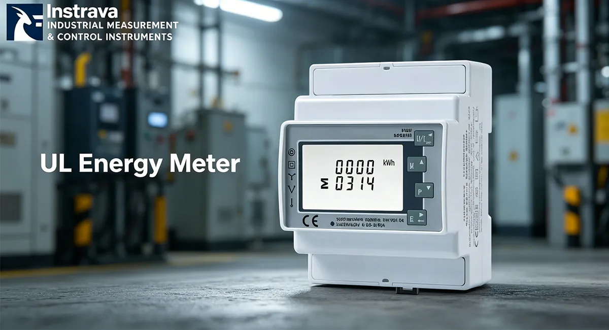
A มิเตอร์ไฟฟ้าอัจฉริยะ is an advanced, microprocessor-based electronic instrument engineered to measure, monitor, and transmit electrical parameters with extreme precision across multi-phase distribution networks. Unlike traditional, legacy induction meters that purely record accumulated active energy consumption on a mechanical dial, modern industrial smart energy meters act as edge-computing data nodes within a facility’s broader Energy Management System (EMS) or Industry 4.0 architecture.
These specialized devices capture full-spectrum electrical metrics in real time, including active energy (kWh), reactive energy (kVarh), apparent energy (kVAh), instantaneous phase voltages, currents, power factors, line frequencies, and total harmonic distortion (THD). Deployed typically via a 35mm DIN rail mounting layout and interfaced with external Current Transformers (CTs), smart energy meters bridge the physical power layer with cloud or on-premise SCADA architectures via integrated communication interfaces like RS485 Modbus RTU. This multi-layered granularity empowers facility engineers to execute precise sub-metering, optimize power distribution, and mitigate peak-demand penalty structures effectively.
2. Traditional Metering Limitations in Harsh Industrial Environments
Heavy manufacturing, automotive plants, and heavy-duty industrial substations subject electrical infrastructure to extreme environmental stresses. In these environments—specifically under High Electromagnetic Interference (EMI) & Harmonic Distortion Environments—traditional electromagnetic induction and basic digital meters routinely fail. Below are the three critical failure modes encountered by legacy systems, alongside the design mechanisms modern smart energy meters use to overcome them:
Problem 1: Core Saturation and Waveform Distortion Blindness
Industrial facilities utilize high concentrations of non-linear loads, such as Variable Frequency Drives (VFDs), switching power supplies, and arc welders. These loads inject extreme harmonic frequencies into the power lines, warping the pure sinusoidal 50/60Hz voltage and current waveforms. Traditional meters rely on primitive averaging or electromagnetic induction techniques that are blind to these high-frequency components. The harmonic waves cause magnetic core saturation in legacy sensor links, resulting in measurement drift, under-reporting, or massive over-reporting of actual energy draw.
The Smart Energy Meter Solution: Advanced smart meters implement high-speed analog-to-digital converters (ADCs) paired with dedicated Digital Signal Processors (DSPs) that sample current and voltage waveforms at rates exceeding several kilohertz. By executing real-time Fast Fourier Transform (FFT) computations, the meter extracts the true Root Mean Square (True RMS) power, precisely capturing every harmonic component up to the 31st or 63rd order, maintaining accuracy despite heavily warped electrical profiles.
Problem 2: Serial Communication Corruption from Common-Mode EMI Noise
Industrial distribution panels are tightly packed environments where low-voltage signal wires run parallel to high-voltage lines feeding heavy machinery. The massive transient electromagnetic fields generated by switching inductive loads introduce devastating common-mode noise across traditional communication networks. Legacy digital meters lacking robust physical layer protection suffer persistent data corruption, packet drops, and continuous communication timeouts, rendering automated sub-metering systems useless.
The Smart Energy Meter Solution: Industrial-grade smart energy meters utilize isolated RS485 transceivers equipped with high-performance optocouplers and integrated Transient Voltage Suppressors (TVS). This design achieves complete galvanic isolation between the internal metering microprocessor and the external communication bus. Even when high-voltage common-mode spikes strike the RS485 data lines, the noise is clamped and safely deflected, ensuring seamless, zero-error Modbus RTU data streaming back to the central gateway.
Problem 3: Thermal Runaway and Phase-Loss Structural Stress
Severe current imbalances between phases are common in facilities running dynamic, unbalanced single-phase auxiliary loads alongside large three-phase machines. This imbalance induces massive neutral currents and localized thermal stress. Traditional meters lack localized thermal management and phase-monitoring safeguards; sustained voltage dips or unbalance induce thermal stress within the meter casing, breaking down component insulation and precipitating early catastrophic device failure.
The Smart Energy Meter Solution: Encased in highly flame-retardant, rugged polycarbonate enclosures optimized for DIN rail thermal dissipation, smart meters are built to endure harsh conditions. They continuously evaluate phase unbalance vectors and generate instant alerts when a critical phase voltage sag occurs. Because the internal power supply module is engineered to operate over an ultra-wide voltage tolerance, the meter remains fully functional and protective even when a complete single-phase loss event hits the distribution panel.
3. International Parameters and Certification Matrix
To safely integrate into global industrial frameworks, a smart energy meter must conform to rigid structural and electrical benchmarks. The following technical matrices define the baseline engineering parameters alongside industry-specific certification mandates required for legal and reliable deployment.
Table 3.1: Baseline Technical Parameters
| Technical Parameter | Standard Engineering Specification |
| โครงสร้างเครือข่าย | Three-Phase Three-Wire (3P3W), Three-Phase Four-Wire (3P4W) |
| ความถูกต้องของการวัด | Active Energy: Class 0.5S (IEC 62053-22), Reactive Energy: Class 2.0 |
| Voltage Input Range | Nominal: 3×230/400V; Operational Range: 70% to 120% of Un |
| Current Input Method | CT Operated (External Current Transformer secondary inputs: 5A or 1A) |
| Communication Protocols | RS485 Serial Interface; Modbus RTU Protocol; Programmable Baud Rates (up to 19200 bps) |
| Mounting Profile | Standard 35mm DIN Rail (Conforming to DIN EN 50022) |
Table 3.2: Sector-Specific Parameters & Certification Standards
| Industry Vertical | Target Parameter Requirements | Critical Certification Mandates |
| Automotive & Heavy Industrial Manufacturing | High Surge Immunity (≥6kV per IEC 61000-4-5); Extended Vibration Resistance; True RMS tracking up to 63rd harmonic order. | UL 61010-1 (Safety Requirements for Electrical Equipment); CE Mark; FCC Part 15 Class B |
| Data Centers & High-Density Computing | Ultra-High Accuracy (Class 0.2S preferred); Sub-second polling interval resolution; Neutral current monitoring capability. | UL Listed; ANSI C12.20 (National Accuracy Standard); RoHS Directive Compliance |
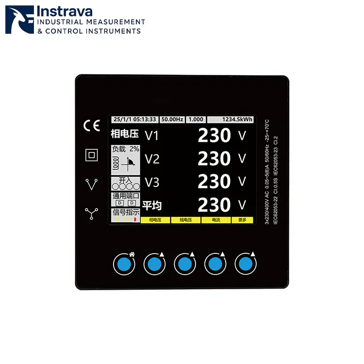
| Renewable Energy Systems (Solar/Wind) | Bi-directional, 4-Quadrant energy tracking; Extended ambient temperature rating ($-25^\circ\text{C}$ ถึง $+70^\circ\text{C}$). | MID Approval (Measuring Instruments Directive 2014/32/EU); CE; UL Certification |
| Commercial Infrastructure & Smart HVAC | Multi-tariff / Time-of-Use (TOU) scheduling engines; Compact multi-module footprint layout. | UL Listed; CE Mark; ISO 9001 Manufacturing Compliance |
4. Instrava Product Showcase: Application Scenario and Compliance Success
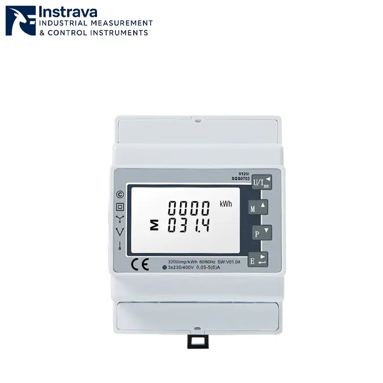
The Instrava UL-Listed Smart Energy Meter stands as a premier example of industrial-grade compliance engineering. By integrating Underwriters Laboratories (UL) certification with a flexible CT-operated architecture, this device delivers seamless integration into complex North American and international grid infrastructures while satisfying stringent local building codes and corporate safety mandates.
Real-World Case Study: Eliminating Harmonic Drift and Securing UL Audit Pass
The Challenge: A Tier-1 automotive parts stamping plant located in Ohio executed an automated energy sub-metering upgrade across its assembly hall. The facility operated 45 high-capacity stamping presses driven by large Variable Frequency Drives (VFDs). These drives generated substantial harmonic noise, which caused their existing non-certified digital meters to experience measurement drift of up to 8.5%, confounding their carbon-accounting metrics. Furthermore, during a routine municipal insurance audit, the facility was flagged for utilizing non-UL-listed instrumentation inside its primary electrical sub-panels, facing a potential plant shutdown if non-compliant hardware was not replaced.
The Solution: The facility replaced its sub-panel infrastructure with the Instrava Three-Phase CT-Operated RS485 Modbus DIN Rail Energy Meter. Because the Instrava meter carries a full UL listing, it cleared the insurance inspector’s safety requirements instantly. The technical team utilized external split-core current transformers clamped around the main incoming busbars, connecting the secondary 5A signal cables directly to the meter terminals. This layout allowed installation to proceed without initiating a costly full-facility power shutdown.
The Result: The embedded DSP inside the Instrava meter completely isolated the harmonic distortion frequencies. Measurement accuracy immediately stabilized back to Class 0.5S parameters, reflecting absolute true energy consumption. By pulling clean real-time data over the RS485 Modbus network into their central SCADA system, the facility identified a major power-factor degradation issue during peak operational hours. Corrective capacitor banks were deployed, leading to a 14% reduction in monthly utility peak-demand charges. The entire project achieved full capital payback within 90 days of deployment while establishing 100% regulatory compliance.
5. Installation Protocols and Environmental Thresholds
To preserve operational safety and retain Class 0.5S accuracy, the physical deployment of a CT-operated smart energy meter must strictly follow standard engineering practices:
Mounting Arrangement: The meter must be securely locked onto a standard 35mm DIN rail inside a protective electrical enclosure. For indoor manufacturing environments, a minimum enclosure rating of IP51 is required; for high-moisture or outdoor applications, an IP65 weather-proof box must be utilized.
Voltage Connection Layout: Phase conductors (L1, L2, L3) and the Neutral wire (N) must be routed to the corresponding voltage sensing terminals through dedicated circuit breakers or inline fuses rated at 1A or 2A. This preserves short-circuit protection at the sensing junction.
Current Transformer (CT) Alignment: External CTs must be installed with precise physical orientation. The side marked P1 (or the source arrow) must face the oncoming utility grid/power source, while the side marked P2 must face the load. The secondary output leads (S1 and S2) must connect to the meter’s current terminals without cross-phasing. Any phase mismatch between voltage taps and CT inputs (e.g., placing L1’s CT onto L2’s input) will disrupt vector calculations and result in highly erroneous readings.
RS485 Bus Topography: Connect the serial lines using a high-quality Shielded Twisted Pair (STP) cable. Daisy-chain multiple meters together in a linear bus configuration. Avoid star or stub topologies, as they trigger signal reflections. A $120\,\Omega$ termination resistor must be wired across the A and B terminals of the physically last meter on the network loop.
6. Preventative Maintenance and Operational Optimization
Although smart energy meters feature solid-state electronic designs with no moving parts, regular maintenance protocols ensure long-term field stability and eliminate measurement errors over multi-year cycles:
Annual Terminal Torque Verification: Industrial environments experience persistent micro-vibrations and thermal expansion cycles. Over time, these forces loosen screw terminals. Technicians must conduct annual torque audits on all voltage and current terminal blocks using a calibrated torque screwdriver, tightening to the manufacturer’s specified torque rating (typically 0.5 to 0.8 Nm) to eliminate high-resistance hot spots.
Infrared Thermal Imaging Audits: During routine facility maintenance windows, utilize a thermal imaging camera to scan the sub-metering enclosure while running under peak load. Any abnormal heat signature concentrated around a terminal indicates a loose contact or wire degradation that requires immediate remediation.
Communication Integrity Monitoring: Implement automated CRC error checking at the SCADA or EMS gateway layer. A sudden increase in Modbus CRC error rates indicates physical degradation of the RS485 cable shielding, moisture intrusion along the bus route, or localized high-frequency EMI infiltration.
Enclosure Cleanliness Protocols: In dust-heavy industrial settings, fine conductive particulates can settle on the meter chassis. Ensure the device exterior is cleaned using dry, low-pressure compressed air or a static-free lint cloth during scheduled panel isolation windows.

Why is the smart energy meter showing a negative active power (kW) or negative energy accumulation value on a specific phase?
A negative active power or negative kW reading on a phase is almost exclusively caused by an inverted Current Transformer (CT) installation. This occurs if the physical CT is clamped backward on the conductor (with the P1/P2 arrow pointing toward the source instead of the load) or if the secondary signal wires (S1 and S2) are reversed at the meter’s current input terminal block. The meter interprets this reversed polarity as power being fed back into the grid, displaying negative metrics. Correcting the physical orientation of the CT or reversing the S1/S2 wiring immediately resolves this symptom.
How do I diagnose and fix persistent "Communication Timeout" or "CRC Errors" on the RS485 Modbus network?
To resolve RS485 Modbus communication issues, execute three diagnostic checks: First, verify via the meter interface that every device on the bus possesses a completely unique Slave ID, and that baud rate, parity, and stop bit configurations match the master gateway exactly. Second, confirm that a 120-ohm termination resistor is wired across the A and B data lines at the absolute physical end of the cable run. Third, ensure that the RS485 communication cable shielding is grounded at only one single point to prevent ground loops from injecting noise into the data packets.
Can a CT-operated smart energy meter be wired directly to a high-current circuit without using external current transformers?
Absolutely not. A CT-operated smart energy meter is engineered with low-impedance internal sensing shunts calibrated strictly for low-amperage secondary inputs (typically a maximum of 1A or 5A, or low-voltage mV signals). Connecting high-current power conductors directly to these current input terminals will induce immediate, catastrophic thermal runaway and vaporize the internal circuitry. This presents an extreme arc-flash and fire hazard. External CTs must always be utilized to scale down high primary industrial currents before routing to the meter inputs.
What does a flashing pulse LED indicate on the front panel of the meter, and why does it sometimes remain completely static?
The flashing pulse LED on the meter front panel serves as a visual indicator of active real-time energy consumption, flashing in accordance with the meter’s defined pulse constant (e.g., 1000 impulses per kWh). If the pulse LED remains completely dark or statically lit, it indicates that either the connected load is entirely turned off, or the current draw falls below the meter’s minimum starting threshold (typically 0.1% of the nominal current rating). If a load is active but the LED remains static, verify that the CT secondary circuits are not short-circuited or disconnected.
What is the technical difference between a UL-listed smart energy meter and a standard CE-marked meter when deploying in North America?
The difference lies in independent third-party safety validation versus manufacturer self-declaration. A CE mark indicates that the manufacturer self-declares compliance with European health, safety, and environmental directives. In contrast, a UL Listing signifies that Underwriters Laboratories has independently tested samples of the device under rigorous safety scenarios to ensure complete compliance with National Electrical Code (NEC) and OSHA safety standards. In North America, utilizing non-UL-listed components inside industrial distribution panels frequently violates building codes, invalidates commercial property insurance policies, and fails mandatory safety audits.
Why is the meter showing highly inaccurate or erratic power factor and total kW readings even though voltage and current values appear normal?
Erratic power factor and highly inaccurate total kilowatt calculations under normal voltage/current levels are classic indicators of a phase-mismatch error. This occurs when a current transformer monitoring one phase is paired with the voltage sensing line of a different phase (for example, wiring Phase A’s CT to the Phase B current input terminal). Because the internal processor multiplies the voltage vector of one phase by the shifted current vector of an incorrect phase, the resulting phase-angle ($\cos\theta$) calculation becomes deeply flawed. Cross-referencing and matching each voltage channel with its corresponding current transformer circuit resolves this error.
ทำไมต้องเลือก Instrava
สร้างบนความสม่ำเสมอ ไม่ใช่คำกล่าวอ้าง
มุ่งเน้นการใช้งานในอุตสาหกรรม
เราเชี่ยวชาญด้านการวิเคราะห์และตรวจจับในอุตสาหกรรม โดยมีความเข้าใจอย่างชัดเจนเกี่ยวกับสภาพแวดล้อมการทำงานจริงและความต้องการต่างๆ.
เกณฑ์การคัดเลือกผลิตภัณฑ์อย่างเข้มงวด
ทุกเครื่องมือได้รับการประเมินตามประสิทธิภาพ, ความเสถียร, และความเหมาะสมในการนำไปใช้—ไม่ใช่เพียงแค่ข้อมูลจำเพาะหรือราคา.
การจัดหาที่เชื่อถือได้และความสม่ำเสมอของคุณภาพ
เราทำงานร่วมกับผู้ผลิตที่เชื่อถือได้เพื่อให้แน่ใจว่ามีปริมาณการจัดหาที่เสถียร คุณภาพที่สม่ำเสมอ และการจัดส่งที่น่าเชื่อถือ.
การสนับสนุนที่ปฏิบัติได้จริงและอิงจากประสบการณ์
คำแนะนำของเราได้รับการสนับสนุนจากความเข้าใจในการใช้งานจริง ช่วยให้ลูกค้าหลีกเลี่ยงปัญหาทั่วไปและบรรลุผลลัพธ์ที่เชื่อถือได้.
Instrava ถูกสร้างขึ้นเพื่อลดความไม่แน่นอน—เพื่อให้ทุกการตัดสินใจของคุณชัดเจน ปลอดภัย และน่าเชื่อถือมากขึ้น.