
Industrial Current Transmitters: Enhancing Power Telemetry and Compliance
1. Introduction: What is a Current Transmitter?
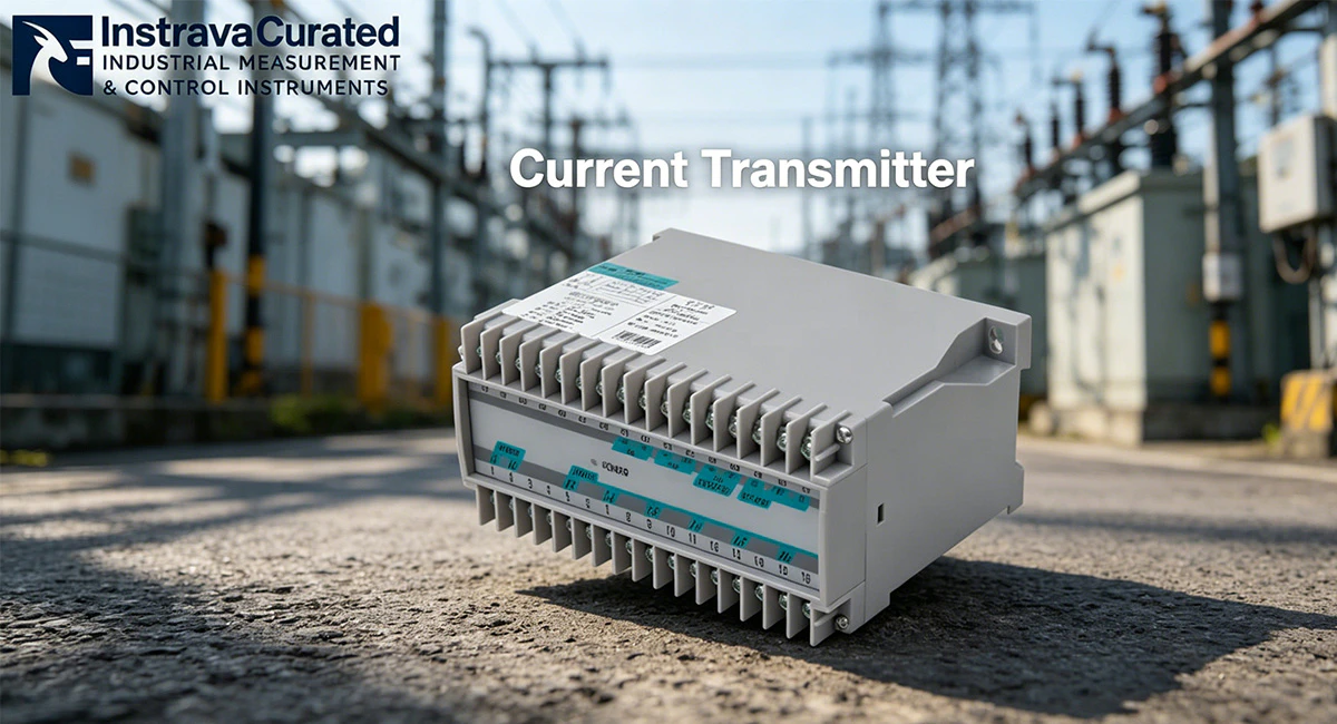
A Current Transmitter (also frequently designated as a current transducer) is a high-precision electrical instrument engineered to detect alternating current (AC) or direct current (DC) signals passing through a conductor and convert them into a standardized, noise-immune output signal. While basic sensors merely detect the presence of electrical current, a sophisticated current transmitter measures the precise electrical waveform, processes the physical parameters, and scales the data into an isolated analog signal (such as 4-20mA or 0-10V) or a digital data stream via an RS485 Modbus RTU protocol interface.
In modern automated industrial environments, multi-phase monitoring is essential. A Three-Phase Current Transmitter RS485 Transducer acts as an edge-computing monitoring node. By interfacing with external current transformers (CTs), this device concurrently samples current vectors across three separate phases. It translates these physical loads into real-time digital registers that can be directly consumed by Programmable Logic Controllers (PLCs), Distributed Control Systems (DCS), or Supervisory Control and Data Acquisition (SCADA) networks, forming a core component of Industry 4.0 power management frameworks.
2. Traditional Technology vs. Modern Transducers in Harsh Industrial Environments
Industrial automated lines, foundry floors, and mining substations subject power monitoring equipment to severe operational stresses. Under High-Transient Electromagnetic Interference (EMI) & Severe Thermal Micro-Vibration Environments, legacy analog current sensors and traditional shunts routinely fail.
Below are the three major problems encountered by traditional monitoring methods, along with the precise engineering mechanisms modern current transmitters use to solve them:
Problem 1: Core Saturation and Linearity Drift Caused by Variable Frequency Drives (VFDs)
Traditional current sensors utilize standard magnetic cores that are highly vulnerable to harmonic frequencies injected by heavy non-linear loads like VFDs and soft starters. These high-frequency currents cause localized magnetic core saturation, which destroys measurement linearity. The result is severe data drift, causing the sensor to output highly inaccurate telemetry that misrepresents actual motor power draw.
The Current Transmitter Solution: Modern three-phase current transmitters utilize advanced high-permeability magnetic alloy cores combined with micro-controlled linear compensation algorithms. By processing signals using high-speed True RMS (Root Mean Square) mathematical engines, the transmitter precisely tracks heavily distorted AC waveforms up to high harmonic orders, maintaining a flat accuracy curve across the entire operational measurement spectrum.
Problem 2: Signal Degradation and Ground-Loop Interference Over Long Distances
Traditional analog current measurement setups that rely on low-voltage analog signals over extended cable runs suffer from voltage drops and signal degradation. Furthermore, potential differences between the ground planes of the physical distribution panel and the control room gateway create ground loops. These loops introduce severe common-mode noise, corrupting the telemetry and rendering the data unusable for automated process control.
The Current Transmitter Solution: Industrial-grade current transducers eliminate this vulnerability by digitizing the raw current telemetry directly inside the monitoring panel. By embedding an isolated RS485 Modbus RTU transceiver, the physical metrics are broadcast as low-impedance differential digital packets. Combined with up to 2.5kV AC galvanic isolation between input, power supply, and communication ports, ground loops are fully broken, ensuring perfect data transmission across distances up to 1200 meters.
Problem 3: Thermal Stress and Terminal Loosening from Structural Micro-Vibration
Heavy industrial machinery creates persistent, low-frequency structural micro-vibrations across distribution switchboards. When combined with the high ambient temperatures inside sealed control cabinets, legacy sensors experience rapid material fatigue. This leads to internal calibration drift and the physical loosening of terminal screw contacts, which can trigger high-resistance electrical arcing faults.
The Current Transmitter Solution: Premium three-phase current transmitters are built inside rugged, flame-retardant polycarbonate housings designed to handle high mechanical vibrations. The internal electronics are securely surface-mounted (SMD technology) and potted or structurally reinforced against vibration. These devices utilize high-torque, vibration-resistant screw terminals or spring-cage clamp mechanisms that maintain constant structural pressure on connection wires, eliminating thermal expansion faults and contact degradation.
3. International Parameters and Certification Matrix
To safely integrate into global automated networks, a current transmitter must comply with standard electrical parameters and international certification frameworks.
Table 3.1: Baseline Technical Parameters
| Technical Parameter | Standard Engineering Specification |
| Input Topology | Three-Phase AC Current Sensing (Phase A, Phase B, Phase C) |
| Primary Current Input | Standardized Current Transformer Secondary Inputs (AC 0-1A or AC 0-5A) |
| Communication Protocol | RS485 Interface, Modbus RTU Protocol (8 Data Bits, 1 Stop Bit) |
| Akurasi Pengukuran | Class 0.5S / Class 0.5 conforming to IEC standards |
| Isolasi Galvanik | ≥ 2500V AC between Input / Output / Power Supply |
| Mounting Configuration | Standard 35mm DIN Rail (Conforming to DIN EN 50022) |
| Auxiliary Power Input | AC/DC 85V – 265V or DC 24V (Application Dependent) |
Table 3.2: Sector-Specific Parameters & Certification Standards
| Industry Vertical | Target Parameter Requirements | Critical Certification Mandates |
| Automotive & Stamping Facilities | High Surge Immunity (≥4kV per IEC 61000-4-5); True RMS harmonic tracking capability. | CE Mark; UL 61010-1 Safety Approval; FCC Part 15 |
| Data Centers & Infrastructure | Sub-second registers sampling; Ultra-low internal power consumption (≤1.5VA). | UL Listed / Recognized; RoHS Compliance; ANSI Standards |
| Metallurgical & Smelting Plants | Extended ambient operating temperature range (-20°C to +70°C); High relative humidity tolerance (95% non-condensing). | CE; Industrial Grade ISO 9001 Production Standards |
4. Instrava Product Showcase: Application Scenario and Compliance Success
The Instrava Three-Phase Current Transmitter RS485 Transducer for Industrial Power Monitoring represents the peak of high-density telemetry engineering. By combining a three-phase multi-channel current acquisition engine with a robust RS485 Modbus output module on a compact DIN rail footprint, this transmitter delivers precise, continuous current analysis without requiring expansive multi-meter panel cutouts.
Real-World Case Study: Resolving Telemetry Chaos in a Heavy Manufacturing Facility
The Challenge: A heavy manufacturing facility operating large industrial induction motors experienced persistent control issues. The high-power auxiliary pumps were injecting substantial electrical noise into the local control cabinets, causing their existing analog current loops to experience severe signal cross-talk and drift. The plant control engineers were receiving erratic, fluctuating current telemetry at the central PLC, which triggered false overcurrent trip sequences and disrupted production. Additionally, the plant required compliance documentation certifying that all low-voltage telemetry components met strict industrial safety standards before a major regulatory facility audit.
The Solution: The engineering team overhauled their monitoring architecture by deploying the Instrava Three-Phase Current Transmitter RS485 Transducer. The transmitter was clipped directly onto the existing 35mm DIN rail inside the motor control center (MCC) panel. The secondary lines from the existing 5A measurement current transformers were routed safely through the Instrava current input terminals. The analog wiring was replaced with a single Shielded Twisted Pair (STP) cable connected to the transmitter’s RS485 port.
The Result: The integrated galvanic isolation and True RMS processing inside the Instrava transducer completely filtered out the common-mode high-frequency noise. Safe, stable, and highly accurate digital current registers were streamed over Modbus RTU back to the master PLC panel. The plant eliminated all false overcurrent tripping events, and the system easily passed the safety compliance audit thanks to the industrial-grade manufacturing standards of the Instrava hardware. The project achieved a total capital return on investment within 45 days through the elimination of unplanned asset downtime.
5. Installation Protocols and Environmental Thresholds
To ensure reliable long-term performance and maintain Class 0.5 measurement accuracy, installation of the three-phase current transducer must follow precise industrial guidelines:
Enclosure and Orientation: Mount the current transmitter on a level section of 35mm DIN rail inside a protective, dust-proof electrical cabinet. For standard dry factory floors, an IP20 or IP51 cabinet enclosure is sufficient. If deploying in a high-moisture, oil-mist, or outdoor setting, the transmitter must be sealed inside an IP65 or IP66 weather-proof control housing.
Current Vector Wiring: Route the current transformer secondary cables (S1 and S2) to the corresponding phase terminals on the transducer block (IA*, IA, IB*, IB, IC*, IC). Ensure the current polarity matches the grid direction perfectly. If the secondary wires of a phase are reversed, the vector angle calculation will be inverted, causing incorrect power and current mapping over the Modbus bus.
RS485 Communication Line Rules: Wire the RS485 network in a strict linear daisy-chain topology from device to device. Avoid star, tree, or long stub branch topologies, as these structural errors trigger data signal reflections. Use high-quality Shielded Twisted Pair (STP) cable with at least 90% shielding coverage. Connect a 120-ohm termination resistor across the A and B communication lines on the physically last transducer in the serial loop to match line impedance.
6. Preventative Maintenance and Operational Optimization
Although solid-state current transmitters do not contain any moving components, regular preventative maintenance steps protect against external environmental stresses and ensure continuous uptime:
Periodic Terminal Torque Inspections: Thermal expansion cycles and industrial plant vibrations can gradually cause screw connections to loosen. Technicians should conduct annual torque checks on all primary current transformer inputs and power terminal connections using a calibrated insulated torque screwdriver to keep connections set to the manufacturer’s specified tension.
Cabinet Dust Mitigation: Conductive factory dust or carbon particles settling over the terminal gaps of the transmitter can form high-resistance tracking paths. Use clean, dry, low-pressure compressed air to clear accumulation from the device face during planned sub-panel isolation maintenance windows.
Communication Quality Tracking: Program the master SCADA or PLC gateway to continuously track CRC (Cyclic Redundancy Check) communication failure rates for each transmitter node. A sudden increase in CRC packet errors indicates physical wear on the RS485 wire insulation, water ingress in the conduit paths, or a failing termination resistor on the loop.
Why is the three-phase current transmitter showing 0A on the RS485 Modbus registers when the primary industrial motor is clearly running?
A zero-current reading on the digital registers under an active load indicates an open circuit or a short circuit along the current transformer (CT) secondary wiring loop. Verify that the shorting blocks on the CT terminals have been physically removed and that the secondary S1 and S2 lines are securely seated into the transmitter’s phase input block. If the connection terminals are secure, use a digital multimeter to measure the AC millivolt or milliamp level directly at the transmitter terminals to confirm if the external current transformer is functioning and outputting signal.
How can a technician eliminate intermittent communication timeouts or data drops on an Instrava current transducer serial loop?
To resolve intermittent RS485 communication timeouts, verify that a 120-ohm termination resistor is wired across the A and B data lines at the absolute physical end of the cable run. Next, ensure that the communication cable shielding is grounded at only one single point, preferably at the master PLC gateway panel, to prevent ground loop currents from overriding the differential data signal. Finally, use the transducer utility configuration tool to confirm that each device on the bus is assigned a completely unique Modbus slave address.
What are the consequences of cross-phasing the voltage reference or current transformer inputs on a multi-phase current transmitter?
Cross-phasing inputs on a multi-phase transmitter occurs when the current transformer monitoring one phase is miswired to a terminal block mapping a different phase channel. While the individual current magnitude values may appear normal, any derived calculations such as three-phase power factor, active power (kW), and reactive power (kVar) will become deeply flawed and inaccurate due to the incorrect 120-degree phase angle vector calculations performed by the internal microprocessor.
Can a high-voltage primary busbar conductor be routed directly into the terminal blocks of a CT-operated current transmitter?
No, high-voltage or high-amperage primary conductors must never be wired directly to the input terminals of a CT-operated current transmitter. These instruments are engineered with low-impedance internal shunts calibrated strictly for low-amperage secondary inputs, typically a maximum of 1A or 5A. Direct connection of primary high-current lines will cause immediate thermal runaway, vaporize the internal circuit traces, destroy the instrument, and pose an immediate risk of an arc-flash explosion or fire.
What causes a current transducer to transmit fluctuating or highly unstable current readings when the physical motor load is running at a constant speed?
Unstable or fluctuating current readings under a constant load indicate severe localized electromagnetic interference (EMI) corrupting the analog signal path before it reaches the transmitter’s processor. This issue occurs when the unshielded secondary wires from the current transformer are routed parallel to high-voltage motor output cables or variable frequency drive (VFD) power lines. Resolving this issue requires routing the CT secondary wires through a dedicated, grounded steel conduit and separating them from high-voltage AC cables by a minimum clearance of 20 centimeters.
Why is an RS485 digital output current transducer preferred over a traditional 4-20mA analog current transmitter in a modern automated facility?
An RS485 digital output current transducer is preferred over a traditional 4-20mA analog transmitter because a single digital unit can transmit multi-phase parameters, including Phase A, B, and C currents, peak demand, and line frequency, simultaneously over a single shielded twisted-pair wire. Traditional analog setups require three separate transmitters and three dedicated sets of PLC analog input cards to monitor a three-phase system, which significantly increases hardware footprints, wiring complexity, and component costs.
Mengapa Memilih Instrava
Dibangun di atas Konsistensi, Bukan Klaim
Berfokus pada Aplikasi Industri
Kami mengkhususkan diri dalam analisis dan deteksi industri, dengan pemahaman yang jelas tentang lingkungan dan persyaratan operasi dunia nyata.
Kriteria Pemilihan Produk yang Ketat
Setiap instrumen dievaluasi berdasarkan performa, stabilitas, dan kesesuaian aplikasi-bukan hanya spesifikasi atau harga.
Konsistensi Pasokan & Kualitas yang Dapat Diandalkan
Kami bekerja sama dengan produsen tepercaya untuk memastikan pasokan yang stabil, kualitas yang konsisten, dan pengiriman yang dapat diandalkan.
Dukungan Praktis dan Berbasis Pengalaman
Rekomendasi kami didasarkan pada pemahaman aplikasi, membantu pelanggan menghindari masalah umum dan mencapai hasil yang dapat diandalkan.
Instrava dibuat untuk mengurangi ketidakpastian-sehingga setiap keputusan yang Anda buat menjadi lebih jelas, aman, dan dapat diandalkan.