
Accueil » Technologie » Transmetteurs de courant industriels : optimisation de la télémétrie de puissance et de la conformité
Transmetteurs de courant industriels : optimisation de la télémétrie de puissance et de la conformité
1. Introduction: What is a Current Transmitter?
A Current Transmitter (also frequently designated as a current transducer) is a high-precision electrical instrument engineered to detect alternating current (AC) or direct current (DC) signals passing through a conductor and convert them into a standardized, noise-immune output signal. While basic sensors merely detect the presence of electrical current, a sophisticated current transmitter measures the precise electrical waveform, processes the physical parameters, and scales the data into an isolated analog signal (such as 4-20mA or 0-10V) or a digital data stream via an RS485 Modbus RTU protocol interface.
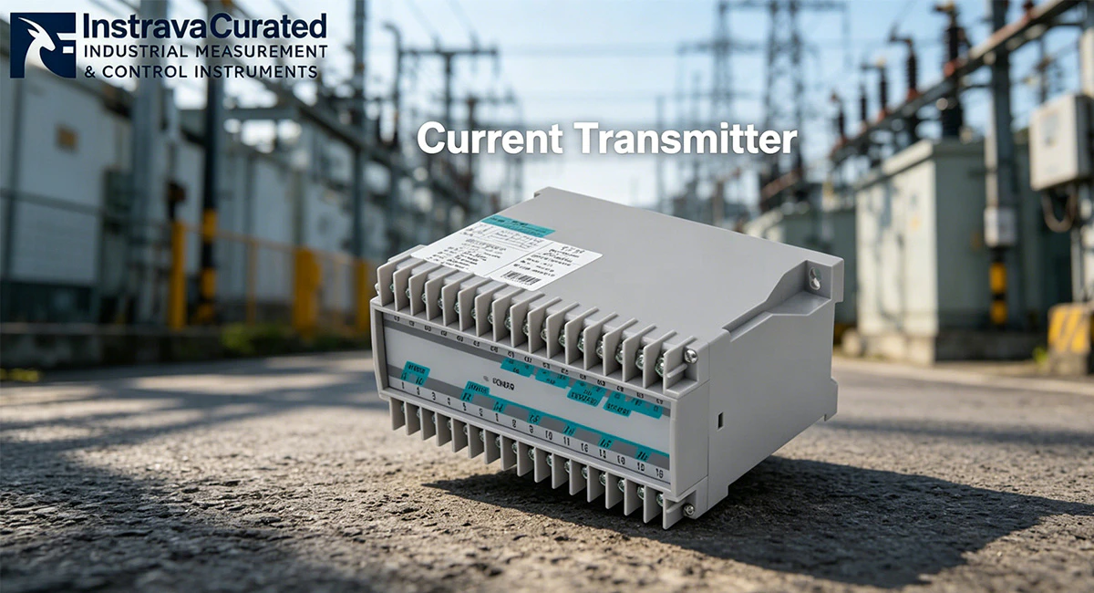
In modern automated industrial environments, multi-phase monitoring is essential. A Three-Phase Current Transmitter RS485 Transducer acts as an edge-computing monitoring node. By interfacing with external current transformers (CTs), this device concurrently samples current vectors across three separate phases. It translates these physical loads into real-time digital registers that can be directly consumed by Programmable Logic Controllers (PLCs), Distributed Control Systems (DCS), or Supervisory Control and Data Acquisition (SCADA) networks, forming a core component of Industry 4.0 power management frameworks.
2. Traditional Technology vs. Modern Transducers in Harsh Industrial Environments
Industrial automated lines, foundry floors, and mining substations subject power monitoring equipment to severe operational stresses. Under High-Transient Electromagnetic Interference (EMI) & Severe Thermal Micro-Vibration Environments, legacy analog current sensors and traditional shunts routinely fail.
Below are the three major problems encountered by traditional monitoring methods, along with the precise engineering mechanisms modern current transmitters use to solve them:
Problem 1: Core Saturation and Linearity Drift Caused by Variable Frequency Drives (VFDs)
Traditional current sensors utilize standard magnetic cores that are highly vulnerable to harmonic frequencies injected by heavy non-linear loads like VFDs and soft starters. These high-frequency currents cause localized magnetic core saturation, which destroys measurement linearity. The result is severe data drift, causing the sensor to output highly inaccurate telemetry that misrepresents actual motor power draw.
-
The Current Transmitter Solution: Modern three-phase current transmitters utilize advanced high-permeability magnetic alloy cores combined with micro-controlled linear compensation algorithms. By processing signals using high-speed True RMS (Root Mean Square) mathematical engines, the transmitter precisely tracks heavily distorted AC waveforms up to high harmonic orders, maintaining a flat accuracy curve across the entire operational measurement spectrum.
Problem 2: Signal Degradation and Ground-Loop Interference Over Long Distances
Traditional analog current measurement setups that rely on low-voltage analog signals over extended cable runs suffer from voltage drops and signal degradation. Furthermore, potential differences between the ground planes of the physical distribution panel and the control room gateway create ground loops. These loops introduce severe common-mode noise, corrupting the telemetry and rendering the data unusable for automated process control.
-
The Current Transmitter Solution: Industrial-grade current transducers eliminate this vulnerability by digitizing the raw current telemetry directly inside the monitoring panel. By embedding an isolated RS485 Modbus RTU transceiver, the physical metrics are broadcast as low-impedance differential digital packets. Combined with up to 2.5kV AC galvanic isolation between input, power supply, and communication ports, ground loops are fully broken, ensuring perfect data transmission across distances up to 1200 meters.
Problem 3: Thermal Stress and Terminal Loosening from Structural Micro-Vibration
Heavy industrial machinery creates persistent, low-frequency structural micro-vibrations across distribution switchboards. When combined with the high ambient temperatures inside sealed control cabinets, legacy sensors experience rapid material fatigue. This leads to internal calibration drift and the physical loosening of terminal screw contacts, which can trigger high-resistance electrical arcing faults.
-
The Current Transmitter Solution: Premium three-phase current transmitters are built inside rugged, flame-retardant polycarbonate housings designed to handle high mechanical vibrations. The internal electronics are securely surface-mounted (SMD technology) and potted or structurally reinforced against vibration. These devices utilize high-torque, vibration-resistant screw terminals or spring-cage clamp mechanisms that maintain constant structural pressure on connection wires, eliminating thermal expansion faults and contact degradation.
3. Paramètres internationaux et matrice de certification
To safely integrate into global automated networks, a current transmitter must comply with standard electrical parameters and international certification frameworks.
Tableau 3.1 : Paramètres techniques de référence
| Paramètres techniques | Spécifications techniques standard |
| Input Topology | Three-Phase AC Current Sensing (Phase A, Phase B, Phase C) |
| Primary Current Input | Standardized Current Transformer Secondary Inputs (AC 0-1A or AC 0-5A) |
| Protocole de communication | RS485 Interface, Modbus RTU Protocol (8 Data Bits, 1 Stop Bit) |
| Précision de la mesure | Class 0.5S / Class 0.5 conforming to IEC standards |
| Galvanic Isolation | ≥ 2500V AC between Input / Output / Power Supply |
| Configuration de montage | Rail DIN standard de 35 mm (conforme à la norme DIN EN 50022) |
| Auxiliary Power Input | AC/DC 85V – 265V or DC 24V (Application Dependent) |
Tableau 3.2 : Paramètres spécifiques à chaque secteur et normes de certification
| Secteur d'activité | Exigences relatives aux paramètres cibles | Obligations essentielles en matière de certification |
| Automotive & Stamping Facilities | High Surge Immunity (≥4kV per IEC 61000-4-5); True RMS harmonic tracking capability. | Marquage CE; UL 61010-1 Safety Approval; FCC Part 15 |
| Data Centers & Infrastructure | Sub-second registers sampling; Ultra-low internal power consumption (≤1.5VA). | Homologué / Reconnu par UL; RoHS Compliance; ANSI Standards |
| Metallurgical & Smelting Plants | Extended ambient operating temperature range (-20°C to +70°C); High relative humidity tolerance (95% non-condensing). | CE; Industrial Grade ISO 9001 Production Standards |
4. Présentation des produits Instrava : cas d'utilisation et réussite en matière de conformité
Le Instrava Three-Phase Current Transmitter RS485 Transducer for Industrial Power Monitoring represents the peak of high-density telemetry engineering. By combining a three-phase multi-channel current acquisition engine with a robust RS485 Modbus output module on a compact DIN rail footprint, this transmitter delivers precise, continuous current analysis without requiring expansive multi-meter panel cutouts.
Real-World Case Study: Resolving Telemetry Chaos in a Heavy Manufacturing Facility
-
Le défi : A heavy manufacturing facility operating large industrial induction motors experienced persistent control issues. The high-power auxiliary pumps were injecting substantial electrical noise into the local control cabinets, causing their existing analog current loops to experience severe signal cross-talk and drift. The plant control engineers were receiving erratic, fluctuating current telemetry at the central PLC, which triggered false overcurrent trip sequences and disrupted production. Additionally, the plant required compliance documentation certifying that all low-voltage telemetry components met strict industrial safety standards before a major regulatory facility audit.
-
La solution : The engineering team overhauled their monitoring architecture by deploying the Instrava Three-Phase Current Transmitter RS485 Transducer. The transmitter was clipped directly onto the existing 35mm DIN rail inside the motor control center (MCC) panel. The secondary lines from the existing 5A measurement current transformers were routed safely through the Instrava current input terminals. The analog wiring was replaced with a single Shielded Twisted Pair (STP) cable connected to the transmitter’s RS485 port.
-
Le résultat : The integrated galvanic isolation and True RMS processing inside the Instrava transducer completely filtered out the common-mode high-frequency noise. Safe, stable, and highly accurate digital current registers were streamed over Modbus RTU back to the master PLC panel. The plant eliminated all false overcurrent tripping events, and the system easily passed the safety compliance audit thanks to the industrial-grade manufacturing standards of the Instrava hardware. The project achieved a total capital return on investment within 45 days through the elimination of unplanned asset downtime.
5. Protocoles d'installation et seuils environnementaux
To ensure reliable long-term performance and maintain Class 0.5 measurement accuracy, installation of the three-phase current transducer must follow precise industrial guidelines:
-
Enclosure and Orientation: Mount the current transmitter on a level section of 35mm DIN rail inside a protective, dust-proof electrical cabinet. For standard dry factory floors, an IP20 or IP51 cabinet enclosure is sufficient. If deploying in a high-moisture, oil-mist, or outdoor setting, the transmitter must be sealed inside an IP65 or IP66 weather-proof control housing.
-
Current Vector Wiring: Route the current transformer secondary cables (S1 and S2) to the corresponding phase terminals on the transducer block (IA*, IA, IB*, IB, IC*, IC). Ensure the current polarity matches the grid direction perfectly. If the secondary wires of a phase are reversed, the vector angle calculation will be inverted, causing incorrect power and current mapping over the Modbus bus.
-
RS485 Communication Line Rules: Wire the RS485 network in a strict linear daisy-chain topology from device to device. Avoid star, tree, or long stub branch topologies, as these structural errors trigger data signal reflections. Use high-quality Shielded Twisted Pair (STP) cable with at least 90% shielding coverage. Connect a 120-ohm termination resistor across the A and B communication lines on the physically last transducer in the serial loop to match line impedance.
6. Maintenance préventive et optimisation opérationnelle
Although solid-state current transmitters do not contain any moving components, regular preventative maintenance steps protect against external environmental stresses and ensure continuous uptime:
-
Periodic Terminal Torque Inspections: Thermal expansion cycles and industrial plant vibrations can gradually cause screw connections to loosen. Technicians should conduct annual torque checks on all primary current transformer inputs and power terminal connections using a calibrated insulated torque screwdriver to keep connections set to the manufacturer’s specified tension.
-
Cabinet Dust Mitigation: Conductive factory dust or carbon particles settling over the terminal gaps of the transmitter can form high-resistance tracking paths. Use clean, dry, low-pressure compressed air to clear accumulation from the device face during planned sub-panel isolation maintenance windows.
-
Communication Quality Tracking: Program the master SCADA or PLC gateway to continuously track CRC (Cyclic Redundancy Check) communication failure rates for each transmitter node. A sudden increase in CRC packet errors indicates physical wear on the RS485 wire insulation, water ingress in the conduit paths, or a failing termination resistor on the loop.
Pourquoi le transmetteur de courant triphasé affiche-t-il 0 A dans les registres Modbus RS485 alors que le moteur industriel principal fonctionne manifestement ?
Une valeur de courant nulle affichée sur les registres numériques en présence d'une charge active indique un circuit ouvert ou un court-circuit au niveau de la boucle de câblage secondaire du transformateur de courant (TC). Vérifiez que les ponts de court-circuit au niveau des bornes du TC ont bien été retirés et que les lignes secondaires S1 et S2 sont correctement enfichées dans le bloc d'entrée de phase du transmetteur. Si les bornes de connexion sont bien fixées, utilisez un multimètre numérique pour mesurer le niveau de courant alternatif en millivolts ou en milliampères directement au niveau des bornes du transmetteur afin de vérifier si le transformateur de courant externe fonctionne et émet un signal.
Comment un technicien peut-il remédier aux délais d'attente de communication intermittents ou aux pertes de données sur une boucle série équipée d'un transducteur de courant Instrava ?
Pour résoudre les problèmes de délais d'attente intermittents dans la communication RS485, vérifiez qu'une résistance de terminaison de 120 ohms est connectée entre les lignes de données A et B à l'extrémité physique absolue du câble. Ensuite, assurez-vous que le blindage du câble de communication est mis à la terre en un seul point, de préférence au niveau du panneau de la passerelle de l'automate maître, afin d'empêcher les courants de boucle de terre de perturber le signal de données différentiel. Enfin, utilisez l'outil de configuration du transducteur pour vérifier que chaque appareil sur le bus se voit attribuer une adresse esclave Modbus totalement unique.
Quelles sont les conséquences d'un déphasage des entrées de la référence de tension ou des transformateurs de courant sur un transmetteur de courant polyphasé ?
Un décalage de phase des entrées sur un émetteur multiphasé se produit lorsque le transformateur de courant surveillant une phase est mal raccordé à un bornier correspondant à un canal de phase différent. Bien que les valeurs individuelles d’intensité puissent sembler normales, tous les calculs dérivés, tels que le facteur de puissance triphasé, la puissance active (kW) et la puissance réactive (kVar), seront gravement erronés et imprécis en raison des calculs vectoriels incorrects de l’angle de phase de 120 degrés effectués par le microprocesseur interne.
Un conducteur de barre omnibus primaire haute tension peut-il être raccordé directement aux borniers d'un transmetteur de courant fonctionnant avec un transformateur de courant ?
Non, les conducteurs primaires à haute tension ou à fort courant ne doivent en aucun cas être raccordés directement aux bornes d’entrée d’un transmetteur de courant fonctionnant avec un transformateur de courant. Ces instruments sont conçus avec des shunts internes à faible impédance, étalonnés strictement pour des entrées secondaires à faible intensité, généralement d’un maximum de 1 A ou 5 A. Le raccordement direct de lignes primaires à courant élevé provoquera un emballement thermique immédiat, vaporisera les pistes des circuits internes, détruira l'appareil et présentera un risque immédiat d'explosion par arc électrique ou d'incendie.
Qu'est-ce qui explique qu'un capteur de courant transmette des valeurs de courant fluctuantes ou très instables alors que la charge physique du moteur fonctionne à vitesse constante ?
Unstable or fluctuating current readings under a constant load indicate severe localized electromagnetic interference (EMI) corrupting the analog signal path before it reaches the transmitter’s processor. This issue occurs when the unshielded secondary wires from the current transformer are routed parallel to high-voltage motor output cables or variable frequency drive (VFD) power lines. Resolving this issue requires routing the CT secondary wires through a dedicated, grounded steel conduit and separating them from high-voltage AC cables by a minimum clearance of 20 centimeters.
Why is an RS485 digital output current transducer preferred over a traditional 4-20mA analog current transmitter in a modern automated facility?
An RS485 digital output current transducer is preferred over a traditional 4-20mA analog transmitter because a single digital unit can transmit multi-phase parameters, including Phase A, B, and C currents, peak demand, and line frequency, simultaneously over a single shielded twisted-pair wire. Traditional analog setups require three separate transmitters and three dedicated sets of PLC analog input cards to monitor a three-phase system, which significantly increases hardware footprints, wiring complexity, and component costs.
Pourquoi faire confiance à Instrava ?
Nous sélectionnons les fabricants en adoptant une approche neutre et impartiale, en gardant toujours à l'esprit vos intérêts.
Notre raison d'être consiste à vous aider à trouver les produits qui répondent parfaitement à vos besoins.
Étant implantés en Chine, nous sommes en mesure de mener des inspections sur place afin d'évaluer directement les conditions de production et la qualité des produits.
Nous vous aidons à éviter les intermédiaires qui se font passer pour des usines.
Nous facilitons un service après-vente plus fluide, en éliminant les problèmes liés aux décalages horaires et les retards souvent associés aux relations directes avec les usines.
Notre équipe multilingue garantit une communication efficace.
Pour une start-up spécialisée dans le trading, chaque interaction avec un client est une occasion précieuse : c’est le signe que vous êtes prêt à nous accorder votre confiance et à nous donner la chance de faire nos preuves.
À l'ère du numérique, alors que l'information est facilement accessible, les idées fausses viennent souvent entacher la confiance entre les gens.
Instrava repose entièrement sur la confiance ; c'est notre philosophie fondamentale et le fondement même de notre existence au sein de la société. C'est le pilier essentiel de notre croissance à long terme et de notre engagement au service de la communauté.
Nous vous prions de nous accorder votre confiance.

Accessibility Settings
Envoyer un message de demande de renseignements
Envoyez-nous vos besoins en matière de fabrication, et notre équipe vous proposera des solutions professionnelles dans les 24 heures.