
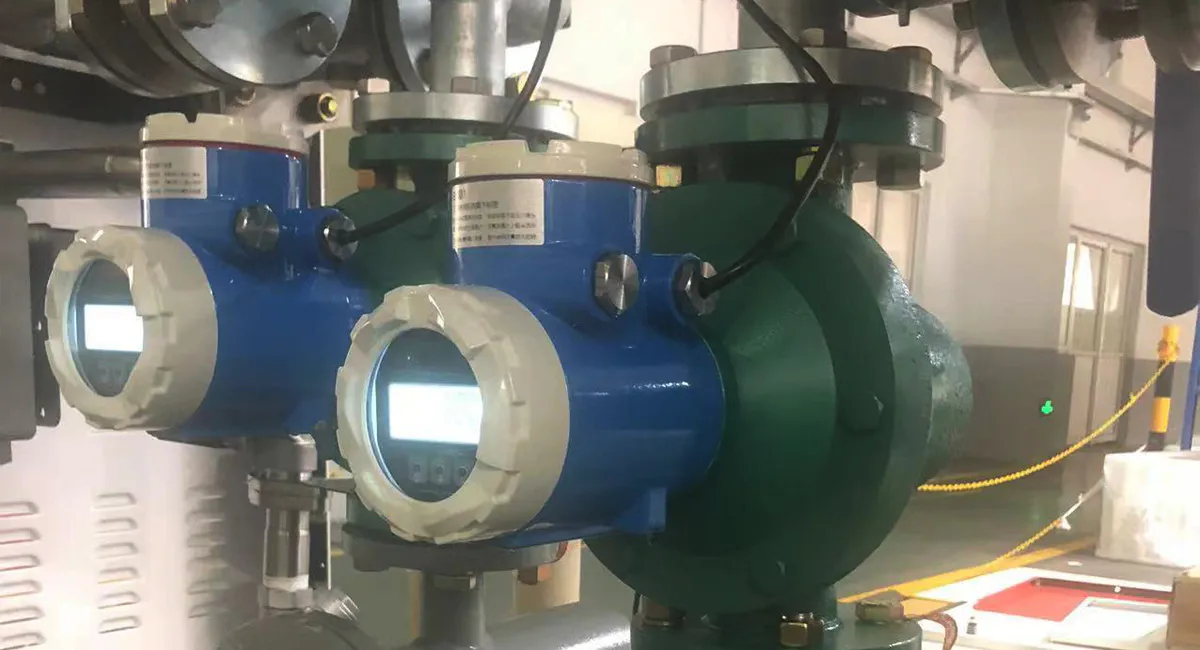
Alat Ukur Aliran Volume Positif – Panduan Lengkap
1. Working Principle, Evolution, and Underlying Reasons
Prinsip Kerja
A Positive Displacement Flow Meter (commonly referred to as a PD flow meter) is often called the “standard measuring cup” of the flow meter world. Its core operation is based on a mechanical measurement method: as fluid passes through the meter, the pressure differential between the inlet and outlet drives mechanical moving components (such as gears, pistons, or rotors). This continuous rotation segments the fluid into discrete, precisely known volumetric “measuring chambers” before discharging it. By accurately recording the number of times these chambers fill and empty, and multiplying that count by the volume of a single chamber, the total volume of fluid passing through the pipe is determined.
Evolution
The evolution of PD flow meters represents a journey from “coarse macroscopic recording” to “microscopic precision metering”:
Ancient Beginnings (Pre-18th Century): The concept originated from ancient water wheels or tipping buckets. Historically, people manually or mechanically counted the rotations of fixed-size containers to measure irrigation water or alcohol for tax collection.
The Industrial Revolution and Public Utilities (19th Century): The rise of urban gas and tap water systems created an urgent demand for automated billing. In the mid-19th century, reciprocating piston water meters dan leather diaphragm gas meters emerged, serving as the ancestors of modern PD meters.
The Oil & Petrochemical Era (Early to Mid-20th Century): The boom of the petroleum industry brought a surge in demand for metering high-viscosity, high-value liquids. Traditional piston designs were bulky and prone to jamming, which spurred the development of oval gear flow meters dan Roots (lobe) flow meters.
Precision Manufacturing and the Digital Age (Late 20th Century to Present): With the proliferation of CNC precision machining and electronic sensors, flow channel designs became optimized (e.g., twin-rotor/screw flow meters). Traditional mechanical counters were replaced by Hall effect sensors, optical encoders, and microprocessors, enabling digital output.
Why Did It Evolve This Way?
This evolutionary path was driven by core technological contradictions and shifting market demands:
From “Intermittent” to “Continuous”: Early piston designs caused severe fluid pulsation (interrupted flow). To minimize the hydraulic shock on processing pipelines, designs gradually transitioned to gears and screws that rotate smoothly and continuously.
Balancing “Low Pressure Drop” and “High Accuracy”: Early mechanical clearances were large, allowing fluid to slip past the rotors (high slippage), which compromised low-flow accuracy. To achieve higher precision, the industry pushed for micron-level machining tolerances to shrink these clearances.
Driven by Medium Diversity: Handling challenging media like crude oil—which contains impurities or exhibits ultra-high viscosity—would instantly jam standard gears. This forced the development of non-contact tooth profiles found in twin-rotor and screw flow meters.
2. Core Technologies, Implementation, and Advantages
The ability of PD flow meters to maintain dominance in high-viscosity, high-precision applications relies on three core technologies:
I. Micron-Level Clearance Control & Dynamic Sealing Technology
How It Is Achieved: The clearance between the measuring chamber wall and the moving rotors is tightly controlled between 5 to 50 microns. High-precision 5-axis CNC machining and grinding ensure that this gap remains constant at every angle of rotation.
Advantage: This micron-level clearance utilizes the viscous resistance of the high-viscosity fluid itself to create a liquid self-seal. Without needing any soft elastomer seals, it minimizes leakage (slippage) and guarantees extreme metering accuracy.
II. Low Starting Torque & Non-Contact Tooth Profile Design
How It Is Achieved: Specially engineered non-circular gears or complex screw profiles (such as involute or cycloid-overlapping profiles) ensure that the rotors engage via a theoretical rolling line contact, or even operate with “zero-contact” driven by external timing gears. This is paired with ceramic bearings or DLC (Diamond-Like Carbon) coatings to minimize friction.
Advantage: This drastically reduces the initial pressure differential required to push the rotors (low starting torque), reduces mechanical wear, and significantly extends the lifespan of the meter.
III. Magnetic Coupling Transmission & Smart Signal Compensation
How It Is Achieved: Rotor movement does not rely on a drive shaft penetrating the housing. Instead, high-strength permanent magnets inside the meter drive external magnetic-sensitive elements (like dual Hall sensors) through a pressure-resistant isolation sleeve. An internal microprocessor applies dynamic slippage compensation based on real-time temperature and pressure data affecting fluid density and viscosity.
Advantage: This achieves a static seal with zero leakage, eliminating the risk of escaping high-pressure or hazardous media. It also removes the frictional load of mechanical counters, improving linearity at low flow rates.
3. Comparison of Common Positive Displacement Flow Meter Types
| Flow Meter Type | Prinsip Pengukuran | Parameter Utama | Media yang Berlaku | Keuntungan | Limitations |
|---|---|---|---|---|---|
| Pengukur Aliran Roda Gigi Oval | A pair of interlocking oval gears rotate alternately driven by the inlet/outlet pressure differential, discharging four chamber volumes per revolution. | • Turndown Ratio: 10:1 to 50:1• Accuracy: ±0.2% to ±0.5%• Temperature: -20°C to 200°C | Clean, high-viscosity liquids such as diesel, heavy oil, resins, and syrups. | • Extremely high accuracy• No straight pipe run requirements• Higher viscosity reduces slippage, improving accuracy | • Unsuitable for media containing solid particles (risk of jamming)• Introduces slight pulsation during operation• Relatively bulky |
| Roots / Lobe Flow Meter | Two figure-8-shaped lobes rotate against each other within the housing, using continuous suction and discharge to measure fluid volume. | • Turndown Ratio: 10:1 to 20:1• Accuracy: ±0.5% (up to ±1% for gases)• Suitable for high-pressure applications | Crude oil, refined oil, and large-flow gases such as natural gas and city gas. | • Large displacement capacity• More robust than oval gear designs• Suitable for large pipe diameters and high flow rates | • Generates notable noise and vibration• Larger rotor clearances reduce low-flow accuracy with low-viscosity media |
| Screw / Helical Rotor Flow Meter | A pair of interlocking helical rotors (similar to a twin-screw pump) move fluid axially in a continuous, pulsation-free manner. | • Turndown Ratio: 50:1 to 100:1• Accuracy: ±0.1% to ±0.2%• Handles viscosities up to tens of thousands of cP | Crude oil custody transfer, premium lubricants, polymers, adhesives, and other high-viscosity fluids. | • Smooth, pulsation-free operation• Low noise• Extremely long service life• Wide turndown ratio• Low pressure drop | • High cost• Complex manufacturing process• Heavy construction |
| Rotary Piston Flow Meter | A piston moves in a combined sliding and rotating parabolic motion within a cylindrical chamber, alternately opening and closing the inlet and outlet ports. | • Turndown Ratio: 30:1• Accuracy: ±0.5%• Typically used in small-to-medium pipe sizes | Tap water, low-viscosity chemicals, and dosing applications in pharmaceutical and chemical processes. | • Excellent low-flow sensitivity• Compact size• Relatively low cost | • Rapid piston wear• Poor tolerance to impurities• Limited to small-to-medium flow rates |
3. Industry Case Study: Problems, Solutions, and Results
4.1 Typical Problem: “High Sand Content and Viscosity Fluctuations” in Crude Oil Terminal Custody Transfer
In crude oil import/export trading or long-distance pipeline custody transfer, the crude oil is not only highly viscous but often carries sand, coke particulates, and free water. Traditional oval gear flow meters frequently suffer from rotor lock-ups dan severe gear face wear, causing a drastic drop in measurement accuracy. Any metering inaccuracies can lead to trade disputes valued at hundreds of thousands of dollars per batch.
Technical Solution (Key Product Design Points)
To address this challenge, the industry developed the “Synchronous Gear-Driven Twin-Screw Flow Meter”:
Key Point 1: Contactless Design (Zero-Contact Screws). High-precision synchronous timing gears are housed outside the wet measuring cell. The rotation of the rotors is driven by these external gears, ensuring that the internal helical measuring rotors maintain a constant 30-micron theoretical clearance and never touch each other.
Key Point 2: Tungsten Carbide Anti-Abrasion Sand Grooves. A high-hardness tungsten carbide (WC) coating is thermal-sprayed onto the rotor surfaces and internal housing walls, alongside micro helical sand-evacuation grooves. When tiny particles enter, they are swept along the grooves by the fluid without damaging the sealing surfaces.
Key Point 3: Multi-Dimensional Dynamic Parameter Matrix Algorithm. The meter features embedded temperature and pressure sensors. To account for the non-Newtonian fluid characteristics of crude oil, a viscosity-temperature curve is programmed into the onboard chip to dynamically correct slippage losses caused by temperature swings.
Final Results
Zero Jams, Maintenance-Free: Even when the crude oil contains trace solid impurities, the flow meter operates continuously and smoothly, eliminating unscheduled shutdowns due to meter lock-ups.
Outstanding Long-Term Stability: After a year of continuous, high-load operation, the lack of mechanical wear between the rotors allowed the measurement accuracy to remain firmly within ±0.15%, satisfying national Tier-1 custody transfer standards.
4.2 Typical Problem: “High Pressure, Chemical Curing/Crystallization, and Micro-Flow Precision Requirements” in PU Foaming
Polyurethane foaming requires mixing isocyanate (black material) dan polyether polyol (white material) at a strict chemical ratio (e.g., 100:30) and instantly injecting the mixture into a mold. This process presents three major pain points:
Media Prone to Crystallization and Jamming: Isocyanate (black material) is hyper-sensitive to moisture in the air. Upon contact with trace moisture, it reacts rapidly to form hard, solid crystals. The dynamic seals of traditional flow meters are prone to microscopic weeping, which introduces air, causes crystallization, and ultimately locks up the meter’s rotors.
High Operating Pressures & Pressure Spikes: To achieve thorough mixing, system operating pressures typically run as high as 15∼25 MPa. High-pressure dosing pumps (such as piston pumps) generate intense pressure pulsations during stroke changeovers, which can easily damage or distort signals from conventional meters.
Extreme Precision for Micro-Flows: Foaming injection is often intermittent, completing a single shot within a few seconds. This requires the flow meter to maintain an accuracy of ±0.2% even at micro-flow rates of just a few milliliters per second. Any ratio imbalance leads to uneven foaming, localized collapse, or improper hardness, causing the product to be scrapped immediately.
Technical Solution (Key Product Design Points of High-Precision Spur Gear Flow Meters)
To withstand this harsh environment, the industry engineered the High-Pressure Sealless Spur Gear Flow Meter:
Key Point 1: Completely Sealless “Magnetic Coupling Static Seal” Design Traditional mechanical seals or packing glands are completely abandoned. The rotor shaft is entirely enclosed within an isolation sleeve made of a high-strength, pressure-resistant alloy (such as Hastelloy). Rotational signals are transmitted to external pickups via magnetic coupling. The entire meter achieves absolute zero external leakage and zero moisture ingress, completely blocking air from reacting with the isocyanate and preventing crystallization-induced lock-ups.
Key Point 2: Tungsten Carbide Bearings & Micron-Level Shock-Resistant Clearances The gears and bearings are fabricated entirely from tungsten carbide or advanced ceramics, offering extreme hardness. The internal clearances are precision-ground to a tight 8∼12 μm. Even if trace hard crystals form due to chemical reactions, the high-hardness gears crush the particulates and flush them away without scratching the measuring chamber.
Key Point 3: Multi-Tooth High-Resolution Sensors (Frequency Doubling Technology) Symmetrical dual Hall sensors or optical sensors are mounted on the exterior of the housing. Rather than just detecting gear teeth, electronic frequency-doubling technology multiplies the pulse count per gear cycle. This enables the meter to instantly capture minute fluid movements within fractions of a second of shot initialization, completely eliminating signal lag.
Final Results
Drastic Drop in Scrap Rates: The meter achieves ±0.2% dynamic ratio control between the black and white materials. This ensures uniform foaming density in automotive seats and insulation boards, dropping batch scrap rates from a historical 3% down to di bawah 0.1%.
Seamless High-Pressure Intermittent Metering: The robust, shock-absorbing spur gear design easily withstands 25 MPa system backpressure and the severe pulsation shocks of piston pumps, delivering a clean, spike-free output signal.
Multi-Fold Extension of Maintenance Cycles: Thanks to the magnetic coupling static seal and tungsten carbide construction, the flow meters operate continuously in highly corrosive, crystallization-prone environments for over 2 years without requiring teardown maintenance. This dramatically improves the uptime and utilization rate of automated automotive and appliance production lines.
5. Technical Bottlenecks and Future Innovative Products
Current Technical Bottlenecks
Despite their high precision, PD flow meters face clear physical bottlenecks under modern, high-precision industrial requirements:
Physical Limits of Mechanical Wear: Because they contain moving parts, minor wear on the bearings and rotors is inevitable over time. As clearances widen, slippage increases, causing “meter drift” that requires regular off-line recalibration.
Low Tolerance to Impurities: When dealing with “dirty fluids” (such as chemical wastewater containing large particles or fibers), high-spec upstream strainers are mandatory. If these strainers clog, they trigger a massive pressure drop in the pipeline.
Cavitation and Pressure Drop at High Flow Rates: When fluid velocity climbs too high, passing through the narrow measuring channels induces a steep pressure drop. In low-boiling-point liquids, this easily triggers cavitation, which can pit and destroy the rotors.
Future Derivative Products & Academic/Technical Trends
To overcome these bottlenecks, academia (such as CFD rotor profile optimization studies published in Flow Measurement and Instrumentation) and industry are co-developing the following next-generation products:
Low-Density, Self-Lubricating Ceramic Rotor Flow Meters
Technical Concept: Replacing stainless steel with advanced engineering ceramics like silicon nitride ($\text{Si}_3\text{N}_4$) or silicon carbide ($\text{SiC}$).
Pain Point Solved: Weight is cut by 60%, minimizing inertia and yielding an ultra-fast response to low flows. Ceramic materials are also highly wear-resistant, corrosion-resistant, and heat-resistant, enabling long-term operation in non-lubricated media.
Self-Diagnostic PD Flow Meters Based on Acoustic Emission and Digital Twins
Technical Concept: Research demonstrates that as rotors wear or fluid slippage increases, specific fluid noise and micro-vibrations are generated. Future products will embed high-frequency acoustic emission sensors within the housing to monitor internal friction and leakage in real time.
Pain Point Solved: By predicting the “health lifespan” of the meter, this technology enables virtual self-calibration without removing the meter from the line.
6. Real-World Application Case Study
Case Background
This case focuses on improving the accuracy of maltose syrup dosing in a mixing process where the syrup accounted for approximately 15% of the total feed entering the mixing vessel. Because the ingredient ratio directly affected product consistency and quality, reliable flow measurement was a critical requirement.
Application Details
Fluid: Maltose Syrup
Temperature: 55°C
Viscosity: Approximately 800 Pa·s (an extremely high viscosity, making the fluid highly thick and sticky)
Density: Approximately 1.35 g/cm³
Pipe Size: DN50 Stainless Steel
Flow Range: 0.5–3 m³/h
Operating Pressure: 2–4 bar(g)
Instalasi: Sanitary Food-Grade Design with CIP (Clean-in-Place) Cleaning
Required Accuracy: Better than ± 0,5%
Selection Logic & Technology Comparison
During the initial phase of the project, process engineers evaluated other mainstream flow measurement technologies, but found them limited by the extreme process conditions:
Electromagnetic Flow Meters: The conductivity of the syrup is extremely low, and the high-viscosity fluid tends to form an insulating coating over the electrodes, preventing measurement.
Coriolis Mass Flow Meters: While highly accurate, forcing a fluid with a viscosity of 800 Pa·s through curved measuring tubes creates an unacceptably high pressure drop. This drop exceeded the head capacity of the feed pump, and the high capital cost exceeded the budget.
Final Choice: Positive Displacement Flow Meter (Sanitary Food-Grade Twin-Screw/Gear Design)
Reasoning: PD flow meters exhibit a unique “inverse viscosity characteristic”—the higher the fluid viscosity, the harder it is for the fluid to leak through the mechanical clearances, resulting in more stable and precise metering. The straight-through design of the DN50 channel combined with smoothly rotating rotors handled the high-viscosity medium at a low pressure drop, and the measurement remained entirely unaffected by the flow profile (operating at an extremely low Reynolds number).
Field Implementation Results
Surge in Dosing Accuracy: The flow meter delivered exceptional repeatability and linearity across the entire 0.5–3 m³/h operating range, keeping the overall dosing accuracy safely within ±0.5%.
Enhanced Batch Consistency: Fluctuations in syrup dosing were reduced to a minimum. The batches produced in the mixing vessel achieved high uniformity in taste and texture, significantly reducing product scrap rates.
Perfect CIP Compatibility: Designed with a crevice-free, food-grade stainless steel architecture, the flow meter could be flushed directly with high-temperature cleaning solutions during CIP cycles, meeting stringent food safety and sanitation standards.
Industry Value: This case proves that for ultra-high-viscosity food ingredients such as maltose syrup, glucose syrup, molasses, honey, and chocolate-based ingredients, Positive Displacement Flow Meters remain the premier solution where precise volumetric measurement and reliable long-term performance are required.
7. Evolution in the Industry 4.0 and AI Era
In the wake of Industry 4.0, the Internet of Things (IoT), and Artificial Intelligence (AI), the PD flow meter—traditionally seen as a purely mechanical device—is undergoing a smart transformation:
[Edge Sensor Acquisition (Flow/Temp/Press/Vibration)] ──> [AI Edge Algorithm (Fluid Characterization & Slippage Correction)] ──> [Digital Twin & Industrial IoT (Predictive Maintenance/Cloud Calibration)]
1. AI-Driven Real-Time “Smart Slippage” Compensation
Traditional PD flow meters rely on fixed empirical formulas for basic temperature and pressure compensation. In the AI era, micro machine learning models (such as neural networks or support vector machines) can be embedded directly within the flow meter or edge gateway.
Implementation: By ingestion of real-time variables—such as pressure, temperature, instantaneous rotational speed, and driving pressure differential—the AI model automatically identifies the real-time viscosity of the fluid (even for complex non-Newtonian fluids) and dynamically calculates and corrects for internal clearance slippage.
Effect: It ensures that the flow meter maintains pristine accuracy even when dealing with variable fluid compositions, oil-water emulsions, or multiphase flows.
2. Predictive Maintenance & Bearing Lifespan Diagnostics
Industry 4.0 emphasizes “zero unscheduled downtime” for equipment assets.
Implementation: High-frequency vibration sensors and micro pressure pulsation sensors are integrated directly into the flow meter housing. AI algorithms analyze the characteristic “acoustic footprint” generated by the spinning rotors. When bearings begin to wear or gears experience micro-chipping, the acoustic signature deviates from its baseline.
Effect: The flow meter flags an alert weeks before an actual failure occurs, reporting messages like: “Bearing life at 10%, please replace during the next scheduled maintenance window.” This shifts plant operations from reactive repair untuk proactive prevention.
3. Digital Twins & Cloud-Based Virtual Calibration
Implementation: A 1:1 digital twin (a physical-mathematical model) is established in the cloud for every PD flow meter shipped. On-site operational data (cumulative total, flow rate, ambient temperature) is fed continuously to the cloud via 5G or industrial Ethernet (e.g., PROFINET, OPC UA).
Effect: The cloud-based digital twin continually evaluates the actual measurement drift based on wear models and operational history. Users no longer need to physically uninstall the meter and send it to a metrology institute. Instead, they can run a “virtual on-line calibration” and compliance check via the cloud, significantly lowering operational costs.
8. Summary
Featuring a unique “measuring cup” mechanical principle, Positive Displacement Flow Meters hold an irreplaceable position in industrial applications demanding high viscosity handling, top-tier accuracy, and independence from straight pipe runs.
From legacy reciprocating pistons to modern, non-contact helical screw rotors, the evolution of the PD flow meter reflects the broader advancements in industrial manufacturing precision. While challenges like mechanical complexity and sensitivity to particulate impurities remain, the integration of Industry 4.0 and AI—coupled with edge computing, acoustic diagnostics, and advanced materials—is turning the traditional mechanical meter into a self-aware, intelligent digital node. It continues to serve as an indispensable cornerstone of precision metering across the process industries.
What kind of operating environment is required for an oval gear positive displacement flowmeter (also known as an Oval flowmeter)?
n oval gear positive displacement flowmeter relies on the tight, interlocking mesh of two elliptical gears. Because of this high-precision mechanical layout, it demands a specific operating environment to maintain its signature accuracy:
Pristine Fluid Cleanliness: The fluid must be completely free of solid particles, abrasives, or fibrous debris. The clearance between the gears and the casing is measured in microns; a single hard particle can wedge into this gap, causing catastrophic scoring or instantly jamming the meter. An upstream strainer (filter) is mandatory.
Medium to High Fluid Viscosity: Oval gear meters thrive on viscosity (e.g., lubricants, heavy oils, syrups, resins). High viscosity acts as a natural liquid seal within the internal clearances. If the medium’s viscosity is too low (like gasoline or light solvents), the fluid will “slip” past the gears, causing the meter to under-register significantly at low flow rates.
Steady Flow Profile (No Dynamic Surges): The environment must be free of sudden, violent flow surges or hydraulic shocks (such as fast-acting valves snapping open upstream). Because the gears have mechanical inertia, sudden spikes in velocity can strip the gear teeth or shear the rotor pins.
Thermal Stability: The fluid and ambient temperatures must remain within the meter’s rated specification. Rapid, extreme temperature fluctuations (thermal shock) can cause the oval gears and the surrounding housing to expand at different rates, leading to either mechanical binding or an excessive clearance gap that ruins accuracy.
Under what operating parameters does a positive displacement flowmeter require maintenance or replacement?
To prevent unexpected failures, keep a close eye on these four telling operational parameters:
Differential Pressure Drop ($\Delta P$): Every PD meter has a baseline pressure drop curve across its operating range. A progressive or sudden increase in this pressure drop at a standard flow rate indicates internal friction, bearing degradation, or debris accumulation choking the measuring chamber.
Low-Flow Accuracy Drift (Slippage): When a PD meter begins under-registering at low flow rates but appears accurate at high flow rates, it means the internal mechanical clearances have widened due to wear. The fluid is slipping through the gaps without turning the rotors.
Acoustic & Vibration Changes: A distinct shift in the meter’s acoustic footprint—such as a metallic clicking, rhythmic grinding, or increased casing vibration—is a direct indicator of bearing wear or rotor misalignment.
Pulse Output Irregularities: For digitally transmitting meters, an uneven pulse train or missing pulses during steady-state pumping indicates either a failing magnetic/optical sensor pickup or eccentric rotor tracking.
What are the solutions if a positive displacement flowmeter generates excessive noise during operation?
Excessive noise in a PD flowmeter is typically a warning sign of a process mismatch or mechanical stress. Here is how to diagnose and resolve it:
Cause: Entrained Air or Gas (The Most Common Culprit)
When gas pockets or bubbles hit the measuring chamber, they compress and expand violently. Worse, because gas offers no viscous resistance, the rotors will overspeed drastically when hitting a dry pocket, making a loud screaming or rattling sound.
Solusi: Install an Air Eliminator or Degasser immediately upstream of the flowmeter. Additionally, increase downstream backpressure using a throttling valve to keep gases dissolved in the liquid phase and suppress cavitation.
Cause: Overspeeding
Operating the meter beyond its maximum rated flow capability forces the mechanical parts to spin too fast, producing a high-pitched whine or roar.
Solusi: Install a flow-restricting or regulating valve downstream to limit the velocity, or resize the pipeline to accommodate a larger flowmeter.
Cause: Upstream Pump Pulsations
Reciprocating, diaphragm, or piston pumps create severe hydraulic pressure pulses that cause the internal rotors of the flowmeter to hammer back and forth.
Solusi: Install a Pulsation Dampener or a flexible surge tank between the pump discharge and the flowmeter inlet to smooth out the flow profile.
Cause: Mechanical Wear
Failing bearings or worn gear profiles create a continuous grinding or clicking sound.
Solusi: Pull the meter offline, open the measuring chamber, and replace the internal bearings, shafts, or rotor assemblies.
What types of media are typically measured using a lobe flowmeter (or Roots flowmeter)? Why is this specific type chosen?
Typically Measured Media
Lobe flowmeters are heavy-duty workhorses utilized across both liquid and gas applications:
Liquids: Crude oil, heavy fuel oil, asphalt, petroleum refining products, and viscous oil-water mixtures.
Gases: High-volume natural gas trunklines, coal gas, city gas distribution networks, and large-scale compressed air lines.
Why This Specific Type is Chosen
Massive Volumetric Capacity: The dual “8”-shaped lobes sweep a significantly larger volume of fluid per revolution compared to oval gears of the exact same nominal pipe size. This makes them ideal for bulk custody transfer in large pipelines.
Low Structural Pressure Loss: The rolling, non-interlocking action of the lobes means the fluid encounters minimal resistance. The resulting pressure drop across a lobe meter is much lower than an oval gear meter, translating to massive energy savings on large-scale operations.
Better Tolerance for Harsh Media: While filtration is still highly recommended, lobe meters engage via a rolling line contact rather than a tight, sliding gear mesh. This allows them to pass highly viscous sludges or fluids with micro-suspended solids far more reliably without locking up.
Distinct Advantages of Scraper (Sliding Vane) Flowmeters
The scraper flowmeter utilizes a central rotor equipped with blades (scrapers) that slide radially in and out as they follow the profile of a cam or eccentric casing wall. It offers several major advantages over other PD types:
[Fluid Inlet] ──> [Scrapers Slide Out against Casing] ──> [Continuous, Pulsation-Free Pocket Transformed] ──> [Fluid Outlet]
True Continuous, Pulsation-Free Discharge: Oval gears and lobe meters exhibit minor, cyclic variations in flow as the teeth engage and disengage. Scraper meters discharge fluid in a perfectly smooth, continuous stream, making them superior for highly sensitive blending systems.
Self-Compensating for Mechanical Wear: This is its finest feature. As the tips of the scrapers wear down over time, centrifugal force or internal springs continue to push the blades outward against the casing wall. The micro-seal is naturally maintained, meaning the meter’s accuracy does not degrade over years of continuous friction.
Excellent Adaptability to Micro-Impurities: Many scraper meters feature graphite or flexible elastic scrapers. If a micro-particle of sand or sediment enters the chamber, the sliding scraper can yield slightly or sweep it cleanly along the hard casing wall rather than jamming like rigid, tightly meshing gears.
Whisper-Quiet Operation at High Flow: Because the parts slide smoothly along a continuous cam track rather than transferring heavy torque loads through interlocking teeth, scraper meters run exceptionally quietly, even at massive flow velocities.
Comprehensive Advantages and Disadvantages of PD Flowmeters
To summarize the technology as a whole, positive displacement flowmeters remain an industry favorite but come with distinct engineering trade-offs:
| Keuntungan | Disadvantages |
| Top-Tier Precision: Exceptional accuracy (frequently $\pm0.1\%$ untuk $\pm0.2\%$) and peerless repeatability, making them the global standard for financial custody transfer. | Heavy and Bulky: The robust metal casings and dense internal rotors make these meters incredibly heavy and difficult to support, especially in larger pipe sizes (DN150 and above). |
| Zero Straight Pipe Requirements: Totally immune to upstream fluid disturbance, swirling, elbows, or nearby valves. You can install them right next to a bend without losing accuracy. | High Pressure Drop: Forcing high-viscosity fluids through narrow internal channels creates a significant pressure drop across the device, demanding larger feed pumps. |
| Thrives on Viscosity: Unlike almost all other flow meter types, their accuracy actually improves as the medium gets thicker because internal fluid slippage approaches zero. | High Vulnerability to Contaminants: A single rogue particle can score the chamber or lock the mechanism, requiring strict, ongoing upstream filter maintenance. |
| Direct Volumetric Readout: Measures actual physical volume directly. Mechanical register versions require zero external electrical power to display totalized flow. | Mechanical Wear Over Time: Moving parts mean unavoidable wear on bearings, shafts, and seals, requiring routine tear-down inspections. |
| Extreme Turndown Ratios: Capable of maintaining high accuracy across incredibly wide flow ranges (up to 100:1 for certain screw designs). | Air/Gas Damage Risk: If a pipeline runs dry or suffers from severe air pockets, the meter will overspeed instantly, often destroying its internal components. |
Mengapa Mempercayai Instrava?
Kami memilih produsen dari sudut pandang yang netral dan tidak memihak, dengan selalu mengutamakan kepentingan terbaik Anda.
Keberadaan kami bergantung pada upaya kami dalam membantu Anda menemukan produk yang paling sesuai dengan kebutuhan Anda.
Berbasis di Tiongkok, kami dapat melakukan inspeksi langsung di lokasi terhadap lingkungan produksi dan kualitas produk.
Kami membantu Anda menghindari perantara yang menyamar sebagai pabrik.
Kami memudahkan layanan purna jual yang lebih lancar, sehingga menghilangkan kendala perbedaan zona waktu dan keterlambatan yang sering terjadi saat berurusan langsung dengan pabrik.
Tim multibahasa kami memastikan komunikasi yang efektif.
Bagi sebuah perusahaan rintisan di bidang perdagangan, setiap interaksi dengan klien merupakan kesempatan yang berharga—sebagai tanda bahwa Anda bersedia mempercayai kami dan memberi kami kesempatan untuk membuktikan diri.
Di era digital, meskipun informasi mudah diakses, kesalahpahaman sering kali mengaburkan rasa saling percaya di antara sesama manusia.
Instrava sepenuhnya bertumpu pada kepercayaan; hal ini merupakan filosofi inti kami dan landasan keberadaan kami di masyarakat. Inilah landasan utama bagi pertumbuhan jangka panjang kami serta komitmen kami untuk melayani masyarakat.
Mohon percayalah kepada kami.