
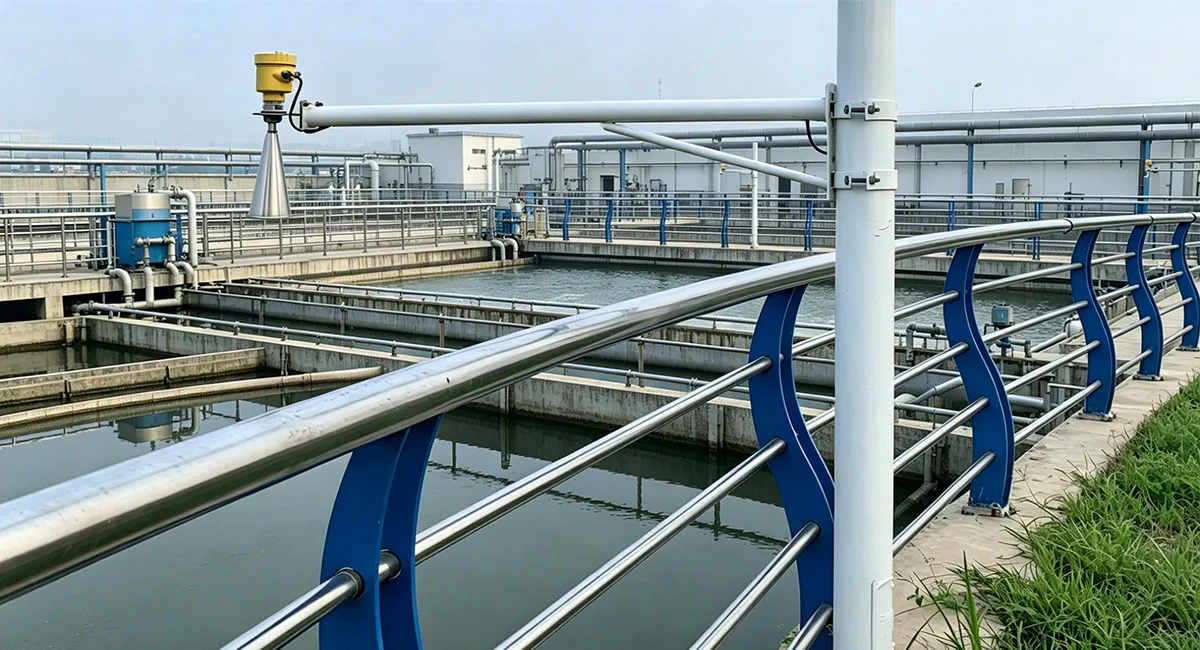
Selecting and Deploying Radar Level Transmitters in Water Treatment Applications
Accurate level measurement is fundamental to automating modern water and wastewater treatment processes. While non-contact radar level transmitters have become the industry standard due to their low maintenance and high reliability, the diversity of water treatment environments—ranging from turbulent open channels to corrosive chemical dosing tanks—demands a precise approach to instrument selection and installation.
This guide outlines the critical technical parameters, application-specific challenges, and deployment best practices required to ensure optimal radar performance in water treatment facilities.
1. Core Technical Selection Parameters
Choosing the right radar technology requires balancing frequency, measurement principles, and material compatibility.
Frequency Analysis: 80 GHz vs. Lower Frequencies (26 GHz / 6 GHz)
The industrial transition toward 80 GHz (Terahertz/Microwave) radar has significantly mitigated historical measurement failures in complex environments, though lower frequencies retain specific niche applications.
| Technical Property | 80 GHz Radar (Recommended Standard) | 26 GHz / 6 GHz Radar |
| Угол луча | Narrow ($3^\circ$ до $4^\circ$); completely bypasses internal obstructions and narrow tank walls. | Wide ($10^\circ$ до $20^\circ$); prone to interference from ladders, pipes, and agitators. |
| Dead Zone (Blocking Distance) | Minimal (typically a few centimeters); allows accurate measurement up to the top of the vessel. | Large (often 20–30 cm or more); limits usable tank capacity. |
| Condensation Management | High signal modulation allows the radar wave to easily penetrate heavy steam and water droplets on the antenna. | Signals attenuate rapidly when heavy condensation or crusting occurs on the lens. |
| Primary Applications | Dosing skids, chemical tanks, wet wells with narrow geometries, and lift stations. | Wide open basins, river water monitoring, large storage reservoirs. |
Measurement Mechanism: Non-Contact FMCW vs. Guided Wave Radar (GWR)
Non-Contact FMCW (Frequency Modulated Continuous Wave): Operates entirely outside the medium, preventing mechanical wear and build-up. This is the optimal choice for raw sewage, sludge, and highly corrosive liquids.
Guided Wave Radar (GWR / Contacting): Utilizes a physical probe (rod or cable) to guide the microwave signal. It is immune to heavy foam and extreme surface turbulence. It is best suited for boiler feed water, demineralized water tanks, or clean water applications where the dielectric constant ($\varepsilon_r$) is very low.
Material Compatibility and Corrosion Resistance
Chemical dosing requires strict isolation of the radar instrument from aggressive media.
Standard Environments (Influent, Effluent, Clarifiers): 316L Stainless Steel process connections.
Corrosive Chemicals (HCl, $\text{NaClO}$, PAC/PAM Dosing): Fully encapsulated plastic antennas (PTFE or PVDF) to guarantee physical protection against acidic or alkaline vapors.
2. Application-Specific Challenges and Solutions
Influent Pump Stations & Mechanical Bar Screens
Process Environment: High velocity, heavy surface debris, rapid level fluctuations, and mechanical rake interference.
Engineering Solution: Deploy an 80 GHz non-contact radar. Its narrow beam can be precisely targeted at the clean water surface immediately before or after the screen, ignoring the movement of the mechanical rake. Outdoor installations should feature a protective sun/rain shield to eliminate temperature-induced transient errors.
Aeration Basins & Anaerobic Digesters (Bioreactors)
Process Environment: Intense surface churning, thick foam blankets, and high humidity. Dense foam acts as a dampener, absorbing and scattering radar signals.
Engineering Solution: For thick, dense foam blankets exceeding 5 cm, standard radars may experience signal loss. The primary fix is utilizing an 80 GHz transmitter engineered with a high dynamic range to process faint return echoes. If foam conditions cause persistent signal loss, install a stilling well (bypass pipe) to isolate a clean, flat liquid surface for measurement (applicable only if the sludge is not prone to heavy crusting or clogging).
Sludge Thickeners and Digester Tanks
Process Environment: Highly viscous media, sticky crust formulation, methane gas generation, and elevated temperatures causing severe condensation.
Engineering Solution: Select a radar utilizing a convex lens antenna (PTFE). The curved, smooth surface prevents water droplets and sludge particulates from adhering to the transmitter face. For high-crusting applications, specify a model with an integrated air purge connection to automate antenna face cleaning via compressed air pulses.
3. Installation and Commissioning Best Practices
Even a perfectly selected instrument will fail if installation standards are neglected. To eliminate common field errors, adhere to the following rules:
Avoid Inflow Streams and Agitator Paths: Never mount a radar directly beneath a fill line or chemical inlet. Falling liquid creates massive false echoes. Furthermore, utilize the transmitter’s internal software to map out fixed obstacles via False Echo Suppression (or Echo Card masking) to ignore agitator blades.
Optimize Nozzle Geometries: Nozzles should be as short and smooth as possible. Internal weld seams or rough edges inside a long nozzle create parasitic reflections. While 80 GHz radars are highly forgiving due to their narrow beam, the best practice is to ensure the antenna tip extends slightly past the bottom of the nozzle neck.
Perpendicular Alignment: Ensure the radar flange or thread is mounted exactly perpendicular to the liquid surface. A tilted instrument causes the microwave energy to reflect away from the receiver, dramatically weakening the return signal.
4. Engineering Workflow for Radar Specification
To standardize procurement and eliminate field errors across water treatment projects, follow this structured validation matrix:
[Chemical Profile Evaluated] ──> Select Antenna Material (316L / PTFE / PVDF)
[Surface Dynamics Checked] ──> Detect Foam/Turbulence ──> Determine need for Stilling Well
[Geometry Mapped] ──> Check Obstructions/Nozzles ──> Define Beam Angle (Prioritize 80 GHz)
[Process Interface Defined] ──> Select Connection Type (Flange / Thread / Bracket)
Почему стоит доверять Instrava?
Мы выбираем производителей, руководствуясь нейтральной и беспристрастной позицией, всегда ставя во главу угла ваши интересы.
Наше существование зависит от того, чтобы помочь вам найти товары, которые идеально соответствуют вашим потребностям.
Благодаря тому, что наша компания базируется в Китае, мы имеем возможность лично проводить проверки производственных объектов и качества продукции на месте.
Мы помогаем вам избежать контактов с посредниками, выдающими себя за заводы.
Мы обеспечиваем более бесперебойное послепродажное обслуживание, устраняя проблемы, связанные с разницей во времени, и задержки, которые часто возникают при непосредственном взаимодействии с заводами.
Наша многоязычная команда обеспечивает эффективное общение.
Для стартапа в сфере трейдинга каждое взаимодействие с клиентом — это ценная возможность, свидетельствующая о том, что вы готовы довериться нам и дать нам шанс проявить себя.
В эпоху цифровых технологий, несмотря на широкую доступность информации, заблуждения зачастую подрывают доверие между людьми.
«Инстрава» полностью опирается на доверие; это наша основная философия и основа нашего существования в обществе. Это фундаментальная основа нашего долгосрочного роста и нашей приверженности служению обществу.
Пожалуйста, доверьтесь нам.