
Главная » Технология » Исследование объемных расходомеров скоростного типа
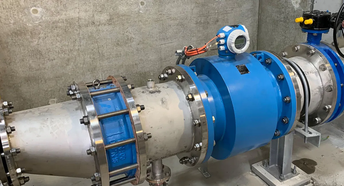
Исследование объемных расходомеров скоростного типа
Введение
Flow measurement is one of the most important variables in industrial automation, alongside pressure, temperature, and level. Accurate flow data directly affects product quality, energy efficiency, process safety, and operational costs.
Among various flow measurement technologies, Velocity-Type Volumetric Flow Meters are some of the most widely used instruments across water treatment, oil & gas, power generation, HVAC, food processing, chemical manufacturing, and industrial utilities.
Unlike positive displacement flowmeters that directly count fluid volume, velocity flowmeters determine the volumetric flow rate by measuring the velocity of a fluid and calculating flow based on the relationship:
Q=A×VQ=A\times VQ=A×V
Где:
- Q = Volumetric flow rate
- A = Pipe cross-sectional area
- V = Average fluid velocity
This principle has evolved into multiple flowmeter technologies, including turbine, vortex, ultrasonic, electromagnetic, and Pitot-based flowmeters, each optimized for different industrial challenges.
1. The Evolution of Velocity-Based Flow Measurement
1.1 Early Mechanical Flow Measurement
Before modern instrumentation, industries relied on:
- Weirs
- Orifice plates
- Venturi tubes
- Mechanical counters
These methods were simple but had several drawbacks:
- High pressure loss
- Ограниченная точность
- Frequent maintenance
- Poor adaptability to changing process conditions
As industrial processes became more complex, engineers needed flow measurement systems that could provide continuous, accurate, and real-time data.
1.2 The Birth of Velocity Measurement
Fluid mechanics research during the 19th and 20th centuries established the relationship between flow velocity and volumetric flow rate.
Instead of directly measuring fluid volume, engineers discovered that measuring fluid velocity could provide a faster and more scalable solution.
This led to the development of:
- Turbine flowmeters
- Электромагнитные расходомеры
- Ультразвуковые расходомеры
- Vortex flowmeters
- Averaging Pitot tubes
1.3 Why Velocity Flowmeters Became Dominant
Compared with traditional methods, velocity-based flowmeters offered:
- Lower maintenance
- Непрерывный мониторинг
- Higher accuracy
- Digital integration capability
- Wider flow ranges
Today, they represent the largest segment of the industrial flow measurement market.
2. Working Principle of Velocity-Type Volumetric Flow Meters
2.1 Fundamental Measurement Principle
Velocity flowmeters determine flow rate by measuring fluid velocity.
Once velocity is known, volumetric flow can be calculated using the pipe’s internal diameter.
The challenge lies in accurately measuring fluid velocity under varying process conditions.
Different technologies achieve this using different physical principles.
3. Core Technologies Behind Velocity Flowmeters
3.1 Velocity Sensing Technology
The primary objective is converting fluid movement into measurable signals.
Methods include:
| Технология | Принцип измерения |
|---|---|
| Turbine | Rotor rotational speed |
| Vortex | Vortex shedding frequency |
| Ультразвуковой | Transit time or Doppler effect |
| Электромагнитный | Faraday’s Law |
| Averaging Pitot Tube | Differential pressure |
| Laser Doppler | Optical velocity measurement |
3.2 Digital Signal Processing (DSP)
Modern flowmeters utilize advanced DSP techniques.
How It Works
The sensor continuously captures raw signals and filters:
- Pipe vibration
- Электрические помехи
- Turbulence effects
- Process disturbances
Преимущества
- Improved accuracy
- Better stability
- Faster response
Industry Problem Solved
Power plants often experience significant vibration and flow fluctuations.
DSP allows stable measurements even in noisy environments.
3.3 Flow Profile Compensation
Fluid velocity is rarely uniform across a pipe.
Elbows, valves, pumps, and reducers distort velocity distribution.
Advanced flowmeters incorporate compensation algorithms.
Research Evidence
The paper “Design of Turbine Flowmeter for Non-Fully Developed Flow Fields” demonstrated that non-uniform velocity profiles significantly affect turbine meter accuracy.
Researchers designed optimized flow straighteners and guide vane structures that reduced repeatability errors by approximately 32.8%, significantly improving performance in disturbed flow conditions.
Преимущества
- Improved accuracy
- Reduced installation constraints
- Better field performance
3.4 Vortex Frequency Extraction Technology
Modern vortex flowmeters use advanced frequency extraction methods.
Research Evidence
The paper “A New Type of Velocity Averaging Tube Vortex Flow Sensor and Measurement Model of Mass Flow Rate” introduced a Velocity Averaging Tube Vortex (VATV) sensor.
Key findings included:
- Accuracy better than ±0.50%
- Repeatability below 0.07%
- Excellent anti-interference capability
- Improved reliability for gas-liquid multiphase flow measurement
This demonstrates how advanced signal processing can significantly improve velocity-based flow measurement.
4. Classification and Functions of Velocity-Type Расходомеры
| Flow Meter Type | Принцип измерения | Типичная точность | Pressure Loss | Движущиеся части | Suitable Media | Ключевые преимущества | Main Limitations | Типовые применения |
|---|---|---|---|---|---|---|---|---|
| Турбинный расходомер | Fluid flow rotates a turbine rotor; rotational speed is proportional to flow velocity. | ±0.2% to ±0.5% | Средний | Да | Clean liquids, fuels, low-viscosity fluids, gases | High accuracy, fast response, wide turndown ratio | Sensitive to flow profile disturbances, mechanical wear, requires clean media | Fuel measurement, custody transfer, chemical dosing, oil & gas |
| Вихревой расходомер | Measures the frequency of vortices generated behind a bluff body (Kármán vortex street). | ±0.5% to ±1.0% | Низкий | Нет | Liquids, gases, steam | No moving parts, excellent for steam measurement, long-term stability | Reduced accuracy at low flow rates, affected by excessive vibration | Steam systems, compressed air, utility monitoring, power plants |
| Электромагнитный расходомер | Based on Faraday’s Law; conductive fluids generate voltage when passing through a magnetic field. | ±0.2% to ±0.5% | Нет | Нет | Conductive liquids, wastewater, slurries | No pressure loss, highly accurate, excellent for dirty fluids | Cannot measure hydrocarbons, gases, or non-conductive liquids | Water treatment, wastewater, mining, chemical processing |
| Ultrasonic Flow Meter (Transit-Time) | Measures difference in ultrasonic signal transit time traveling upstream and downstream. | ±0.5% to ±1.0% | Нет | Нет | Чистые жидкости | Clamp-on installation available, no pipe cutting, no pressure loss | Requires relatively clean fluid, affected by air bubbles | Water distribution, HVAC, district cooling, industrial water systems |
| Ultrasonic Flow Meter (Doppler) | Measures frequency shift caused by particles or bubbles moving with the fluid. | ±1% to ±3% | Нет | Нет | Dirty liquids, slurries, wastewater | Suitable for fluids containing solids or bubbles | Lower accuracy than transit-time ultrasonic meters | Wastewater, mining slurry, dredging applications |
| Averaging Pitot Tube Flow Meter | Measures differential pressure between impact and static ports to determine average flow velocity. | ±1% to ±2% | Очень низкий | Нет | Liquids, gases, steam, air | Low cost, simple installation, minimal pressure loss | Lower accuracy compared to other technologies | HVAC, flue gas monitoring, ventilation systems |
| Laser Doppler Flow Meter | Uses laser beams to measure Doppler shift caused by moving particles in the flow. | ±0.1% to ±0.5% | Нет | Нет | Liquids and gases with reflective particles | Extremely high precision, non-contact measurement | Expensive, mainly used in research environments | Laboratory testing, aerospace, flow research |
| Insertion Velocity Flow Meter | Measures local velocity at a specific point and calculates total flow using velocity profile models. | ±1% to ±2% | Очень низкий | Нет | Water, gases, steam | Suitable for large pipes, low installation cost | Accuracy depends on flow profile assumptions | Municipal water systems, large pipelines, industrial utilities |
Extend:
4.1 Turbine Flow Meters
Problem Solving & Academic Validation: Traditionally excellent for high-precision totalization of low-viscosity, clean fluids. However, real-world industrial spaces (taking a standard DN25 line as a benchmark) are highly cramped, forcing meters to sit immediately downstream of a 90° single elbow, which generates a severely 流场非充分发展 (non-fully developed flow field).
Validation via Academic Research: Empirical studies on non-fully developed flow fields confirm that the length of the straight pipe run following an elbow drastically impacts the meter’s characteristic curve, average meter factor, linearity error, and repeatability error. To counter this, recent research introduced a key diagnostic metric called the “Stationary Coefficient.” Through coupled Computational Fluid Dynamics (CFD) modeling and physical testing, an optimized architecture was developed: incorporating a 3 mm thick rectifier paired with a reduction of the internal guide vane length to 2 mm.
Resolution Effect: Implementing this precise flow-conditioning geometry allows the turbine flow meter to achieve an average reduction in repeatability error of 32.80% when installed in complex, non-fully developed flow conditions. This dramatically enhances measurement stability and precision across tightly packaged piping manifolds, solving the historical issue of measurement distortion caused by restricted straight runs.
4.2 Vortex Flow Meters
Problem Solving & Academic Validation: Ideal for high-temperature, high-pressure gas and steam applications due to its completely non-moving internal design. However, conventional combined multi-instrument setups face severe accuracy degradation when subjected to wet steam, gas-liquid two-phase flows, or intense industrial piping vibrations.
Validation via Academic Research: To break through this bottleneck, researchers engineered a Velocity Averaging Tube Vortex flow sensor (VATV) backed by an integrated mass flow rate measurement model. This fully integrated VATV sensor features zero internal moving parts and introduces a “Double Differential Pressure Method.” This technique simultaneously captures an average differential pressure signal and a differential pressure fluctuation signal. An Empirical Wavelet Transform (EWT) algorithm is then deployed to extract the exact vortex shedding frequency directly from the high-noise fluctuation signal.
Resolution Effect: Physical verification shows that this integrated technique delivers an accuracy of ±0.50% for mass flow rate with a repeatability below 0.07%, marking a profound upgrade over loose, unintegrated combined instruments. Because of its robust anti-interference characteristics and structural reliability, it successfully solves the industry-wide headache of tracking gas-liquid two-phase flows such as wet steam.
5. Industry Pain Points and Core Technical Solutions
The application of these core technologies provides direct solutions to chronic pain points across several major processing and manufacturing sectors:
5.1. Oil & Gas Custody Transfer and High-Precision Transport
Specific Industry Problem: Natural gas and crude oil are high-value commodities. In pipeline compression and distribution stations, space is at a premium, piping layouts are complex, and elbows are tightly packed, rendering the flow field non-fully developed. Furthermore, long-distance transmission introduces heavy high-frequency vibrations from upstream compressors. If a meter’s repeatability drifts even slightly, the resulting “unaccounted-for gas/oil” discrepancy can lead to massive commercial financial disputes.
Technical Solution: Deploying flow conditioning technology (optimized rectifiers and blade profiles) coupled with multi-path transit-time ultrasonic flow meters. Flow conditioning structures neutralize upstream swirl, ensuring a symmetrical velocity profile entering the acoustic paths, while non-contact ultrasonic arrays avoid adding line pressure drop.
Resolution Effect: Ensures that custody transfer meters maintain ultra-low repeatability errors and long-term zero-point stability, even within highly chaotic piping networks.
5.2. Saturated and Superheated Steam Metering in Power & Chemical Sectors
Specific Industry Problem: Steam serves as the primary energy carrier in chemical plants and power generation facilities. It features high temperatures (often exceeding 200°C) and high velocities, and poor insulation along long pipe runs frequently creates “wet steam” (a gas-liquid two-phase flow). Traditional meters subjected to wet steam generate false readings due to liquid droplet impacts on the sensor elements and fail to capture actual energy/mass loss driven by fluctuating dryness fractions.
Technical Solution: Utilizing composite aerodynamic fluid oscillation sensors (such as integrated velocity-averaging tube and vortex structures). These designs use rugged, impact-resistant geometries to withstand two-phase fluid hammering alongside advanced frequency-extraction algorithms to isolate and filter out droplet noise.
Resolution Effect: Achieves stable metering of wet steam and two-phase flows under intense interference, heavily sharpening the accuracy of plant-wide energy efficiency audits.
5.3. Plant Gas Utility Management in Metallurgy and Manufacturing
Specific Industry Problem: Compressed air, nitrogen, and argon are among the highest-overhead utility expenses in modern manufacturing plants. Internal workshop piping is a labyrinth of tight spaces with almost zero straight pipe runs. Traditional velocity meters lose their linearity when straight runs are short, preventing precise cost allocation across different manufacturing cells and handicapping corporate carbon and energy reduction initiatives.
Technical Solution: Introducing velocity-type meters featuring low-flow startup optimization and built-in flow conditioning modules.
Resolution Effect: Bypasses the spatial limitations of short straight pipe runs, sustaining tight linearity even in sub-optimal installations to provide trustworthy, granular consumption data across factory lines.
6. Technical Bottlenecks and Future Product Evolution Predictions
6.1 Current Technical Bottlenecks
Physical Model Breakdown under Extreme Multi-Phase Flow: While specific velocity meters have carved out niches in low-moisture gas or wet steam, they stumble when encountering high-sand crude oil, high-viscosity foaming liquids, or true oil-gas-water three-phase mixtures. The heavy presence of multiple phases warps fluid oscillation structures, scatters and attenuates ultrasonic energy, and invalidates standard velocity-to-volume mapping equations.
Non-Linearity at Ultra-Low Reynolds Numbers: Velocity meters require the fluid to operate within a stable, fully turbulent regime. At very low velocities or high fluid viscosities, the flow transitions toward a laminar state. The Reynolds number drops into a critical zone where the meter factor fluctuates wildly, undermining linearity and compromising wide turndown capabilities.
Long-Term Geometric Erosion and Chemical Scaling: In continuous-operation chemical or metallurgical loops, even meters without moving parts suffer over time. The sharp edges of vortex bluff bodies round off due to particle erosion, and chemical scaling or crystallization alters the true internal cross-sectional area of the pipe. These uncompensated changes in internal geometry lead to a slow, irreversible calibration drift.
6.2 Future Product Evolution Predictions
Driven by advances in materials science, optoelectronics, and quantum sensing, the next generation of velocity-type flow meters will likely see the birth of highly advanced architectures:
Product Evolution 1: Non-Invasive “Acoustic Tomography” Panoramic Flow Meters
Features: Utilizing an external clamp-on array of high-density ultrasonic transducers combined with computerized industrial tomography. This meter will dynamically reconstruct a full 3D cross-sectional view of the pipe interior in real time. It will not only calculate velocity profiles but also map out phase interfaces, enabling non-destructive, highly precise tracking of complex multi-phase streams without cutting into the line.
Product Evolution 2: Quantum Coherent / Fiber-Optic Laser Doppler Flow Meters
Features: Utilizing fiber-optic Bragg gratings or micro-laser Doppler anemometry to completely remove electronic components from the physical fluid line. These meters will offer total immunity to electromagnetic interference (EMI) and operate in extreme thermal environments (withstanding super-critical fluids up to 600°C), opening new doors for hydrogen transport networks and nuclear cooling loops.
7. Industry Problem, Selection Strategy, and Technical Parameter Matrix
The following matrix maps out typical industrial fluid challenges, matching them to optimized velocity-type flow configurations and their core technological specifications:
| Target Industry | Specific Field Problem | Recommended Flow Meter Type | Core Technical Parameter Requirements | Key Parameter Function Description |
| Fine Chemicals / Power & Utilities | Saturated/superheated steam billing; high ambient piping vibration; presence of gas-liquid two-phase flow (wet steam). | Advanced Velocity Averaging Tube Vortex Mass Flow Meter (VATV) | Accuracy: ±0.50% (Mass)Repeatability: ≤0.07%Internal Structure: Integrated, no moving partsSignal Capture: Double DP + EWT Algorithm | Tight accuracy and low repeatability secure fair energy accounting; dual-differential pressure sensing and EWT wavelets completely isolate process signals from structural piping noise. |
| Oil & Gas Transport (Pumping Stations) | Highly cramped footprints with short straight runs; 90° bends creating non-fully developed flow; high-stakes custody transfer. | Low-Distortion Sensitive Turbine Flow Meter (With Integrated Rectifier Optimization) | Accuracy: ±0.2%Repeatability Error: Reduced by 32.8% on averageConfiguration: 3mm Rectifier + 2mm Short VanesStraight Pipe Requirement: Upstream ≤5D | Custom inlet conditioning geometries dramatically lower the meter’s sensitivity to installation anomalies (Stationary Coefficient reduction), guaranteeing premium repeatability with short straight runs. |
| Municipal Water / Bulk Crude Mains | Extremely large lines (DN500+); zero downtime allowed for installation; strict mandates against line pressure drop. | Multi-Path Transit-Time Ultrasonic Flow Meter (Clamp-on / Insertion) | Accuracy: ±0.5%Acoustic Array: 4 to 8 pathsPressure Drop: 0 (No obstruction)Turndown Ratio: 1:100 | Multi-path layouts deploy numerical integration to cancel out velocity asymmetry across large cross-sections; zero pressure drop yields massive annual energy savings. |
| Shale Gas / Unconventional Upstream | Low wellhead gas velocities with wide surge cycles; presence of minor composition shifts and pressure pulsations. | Smart Swirl Flow Meter | Accuracy: ±1.0%Turndown Ratio: up to 1:30Straight Pipe Run: Upstream 3D / Downstream 1DIntegration: Built-in Temp/Pressure Compensation | Ultra-low velocity cut-ins capture weak gas production; high turndown spans daily flow swings; exceptional internal swirl mechanics eliminate reliance on long straight runs. |
8. Evolution in the Era of Industry 4.0 and AI
As Industry 4.0 matures and Artificial Intelligence (AI) integrates into edge devices, velocity-type volumetric flow meters are rapidly transforming from passive hardware sensors into intelligent edge-computing nodes and flow-regime diagnostic centers:
8.1 Edge AI and Hardware-Level Signal Decoupling
Traditional digital filtering processes are constrained by fixed frequency cutoffs. Next-generation velocity meters embed lightweight neural networks (TinyML) directly onto native microchips. The AI learns the exact “vibrational footprint” and “acoustic baseline” of a specific pipe asset under nominal states. When anomalies like cavitation, flashing, or structural bolt loosening occur, the edge AI separates the true velocity frequencies from chaotic, state-dependent background noise. Moving past rigid mathematical wavelets, the system dynamically alters its filtering profiles to match changing flow regimes.
8.2 Digital Twin-Driven Online Flow Field Virtualization
In an Industry 4.0 environment, flow meters no longer operate in information silos. The meter links over high-speed industrial networks with upstream smart valves, pumps, and downstream process geometry to form a localized Цифровой близнец. By feeding real-time multi-path acoustic arrays or differential pressure fluctuations into an edge-running, Reduced-Order Model (ROM) derived from Computational Fluid Dynamics (CFD), the software reconstructs a live 3D velocity profile of the internal stream. Even if physical space constraints force a sub-optimal installation, the digital twin calculates the real-time distortion index, automatically injecting corrections to preserve high precision.
8.3 Full Lifecycle Prognostics and Health Management (PHM)
AI-enabled velocity meters bring native self-diagnostic intelligence into the plant loop:
Turbine Instruments: By tracking tiny micro-deformations in the electromagnetic wave shape produced by the rotor blades, an AI can diagnose bearing friction build-up, flagging maintenance tickets weeks before an actual mechanical seizure occurs.
Ultrasonic Instruments: By checking shifts in signal gain profiles and signal-to-noise ratios (SNR), the onboard AI automatically determines if a transducer face is experiencing chemical scaling or localized pitting corrosion, prompting an automated flush cycle.
9. Заключение
As fundamental pillars of modern process automation, velocity-type volumetric flow meters continue to evolve in lockstep with industry’s push for extreme accuracy, high operational uptime, minimal pressure drop, and digital transparency. From early mechanical turbines to fluid-dynamic vortex models and non-contact ultrasonic arrays, every structural leap has aimed to neutralize pressure loss, eliminate mechanical wear, and master fluid profile variations.
Recent academic breakthroughs demonstrate that blending multiple physical sensing techniques—such as Velocity Averaging Tube Vortex (VATV) architectures—alongside advanced geometric re-engineering (like rectifier/blade optimizations that slice bend-induced repeatability errors by 32.80%) successfully resolves chronic field issues involving complex flow profiles and two-phase mass flow determination.
Entering the Industry 4.0 and AI eras, these devices are transitioning into decentralized intelligence hubs leveraging TinyML and digital twins. The velocity meter of tomorrow will step beyond its role as a simple pipe component, casting off strict straight-run dependencies to act as a self-filtering, self-healing, and deeply predictive diagnostic engine for global smart factories.
(Includes some quick selection guides)
| Application Requirement | Recommended Velocity Flow Meter |
|---|---|
| Highest accuracy for clean liquids | Турбинный расходомер |
| Steam measurement | Вихревой расходомер |
| Wastewater and slurry measurement | Электромагнитный расходомер |
| Large pipeline without shutdown | Clamp-on Ultrasonic Flow Meter |
| Dirty liquid containing solids | Doppler Ultrasonic Flow Meter |
| Low-cost airflow monitoring | Averaging Pitot Tube |
| Scientific and laboratory measurements | Laser Doppler Flow Meter |
| Large-diameter municipal pipelines | Insertion Velocity Flow Meter |
Technology Selection by Medium
| Medium Type | Best Technology |
|---|---|
| Clean Water | Electromagnetic / Ultrasonic |
| Сточные воды | Электромагнитный |
| Пар | Vortex |
| Сжатый воздух | Vortex / Pitot Tube |
| Fuel Oil | Turbine |
| Chemical Liquids | Electromagnetic / Ultrasonic |
| Шлам | Электромагнитный |
| Large-Diameter Water Pipelines | Ультразвуковой |
| HVAC Airflow | Pitot Tube |
| High-Precision Research Applications | Laser Doppler |
Which type of flow meter can measure water flow without being affected by particulate matter in the water?
If you are dealing with water packed with suspended solids, sand, or debris, you have two primary options depending on the exact measurement technology required:
The Gold Standard: Electromagnetic Flow Meters (Magmeters) While not a velocity-type meter in the acoustic or mechanical sense, a magmeter is the absolute best choice for dirty water. It features a completely unobstructed, straight-through flow tube with no moving parts or probes protruding into the stream. Because it operates on Faraday’s Law of Electromagnetic Induction, the particulate matter does not affect the measurement as long as the fluid remains electrically conductive.
The Velocity-Type Alternative: Doppler Ultrasonic Flow Meters If you must use a velocity-type meter, Doppler ultrasonic meters are explicitly designed for this scenario. Unlike transit-time ultrasonic meters (which require clean liquid), Doppler meters need particles, sediment, or air bubbles to act as acoustic reflectors. The sensor measures the frequency shift of the sound waves bouncing off these moving particles to calculate fluid velocity.
Совет профессионала: Avoid turbine or standard vortex meters for high-particulate water. Particles will rapidly erode or jam turbine bearings and clog the pressure ports or wrap around vortex bluff bodies.
What are the primary reasons for low measurement accuracy and poor operational stability in velocity-type flow meters?
Velocity-type meters infer volume by sampling fluid speed. Because they rely heavily on predictable fluid dynamics, their accuracy and stability are vulnerable to five main culprits:
Distorted Flow Profiles (The #1 Killer): Bends, valves, pumps, and reducers upstream create severe swirl and asymmetric velocity profiles. If the velocity distribution entering the meter is distorted, the sensor samples a non-representative flow speed, causing heavy measurement drift.
Fluid Viscosity Shifts & Low Reynolds Numbers: Velocity meters are calibrated for turbulent flow regimes where the velocity profile is relatively flat. If fluid viscosity spikes or the flow rate drops significantly, the flow transitions toward a laminar regime (low Reynolds number), causing the meter factor to fluctuate wildly.
Mechanical Wear and Sensor Fouling: For mechanical types like turbines, bearing wear increases rotational friction over time, leading to under-reporting. For non-contact types, chemical scaling, rust, or bio-waxes coating the sensor elements (or pipe walls in ultrasonic styles) attenuate signals and alter internal pipe geometry.
Environmental and Piping Interference: Vortex flow meters are highly sensitive to pipe vibrations, which can be misread as vortex shedding frequencies. Similarly, turbine and ultrasonic meters can have their signal pulses corrupted by nearby high-power electromagnetic interference (EMI) from variable frequency drives (VFDs).
Entrained Gas or Phase Changes: Small pockets of trapped air in a liquid line (or liquid droplets in a gas line) scatter ultrasonic signals and disrupt vortex generation, leading to erratic readings or complete signal loss.
When a purchased vortex flow meter's diameter is larger than the pipeline diameter, can it be installed and used? If it cannot be used directly, how should it be handled (without returning it)? What are the consequences of forcing it into use? Can it be used?
No, it cannot be directly installed and used without modification. However, you do not have to discard it. You can adapt the piping to match the meter.
How to handle it correctly on-site:
You must install concentric pipe reducers (pipe expanders) upstream and downstream of the flow meter.
Upstream: Install a smooth, concentric expander to transition the smaller pipe diameter up to the larger meter size. You must ensure a straight run of at least 20D (20 times the pipe diameter) after the expander before reaching the meter inlet to allow the flow profile to stabilize.
Downstream: Install a concentric reducer to bring the pipe diameter back down to the original line size, maintaining at least 5D of straight pipe between the meter outlet and the reducer.
Consequences of forcing it into use (Direct/Abrupt Installation):
If you force it into the line using abrupt flange adapters without sufficient straight runs, you will face disastrous operational issues:
Complete Signal Loss at Low Flows: Fluid velocity drops significantly when transitioning into a wider pipe section ($v \propto 1/A$). If the velocity drops below the meter’s minimum threshold, the fluid will fail to generate vortices against the bluff body, resulting in a zero reading even though fluid is moving.
Severe Flow Separation and Eddies: The sudden expansion creates massive fluid separation, localized turbulence, and back-eddies directly at the face of the meter. The vortex shedding frequency will become completely chaotic, rendering the meter readings wildly inaccurate and unstable.
What causes unstable readings in clamp-on ultrasonic flow meters, and how can they be resolved?
| Identified Cause | Recommended Technical Solution |
| Acoustic Couplant Degradation: The gel between the transducer face and the pipe wall has dried out, cracked, or washed away, leaving air gaps that block ultrasonic waves. | Clean the pipe surface and transducer faces thoroughly. Reapply a high-quality acoustic couplant (or use permanent silicone/solid pads for long-term installations) and clamp tightly. |
| Internal Pipe Scale or Lining Gaps: Heavy rust, scale buildup, or a detached internal mortar/plastic liner creates an air pocket or attenuates the sound path. | Move the transducers to a cleaner, newer section of the pipe network. If relocation is impossible, grind the outer pipe down to bare, shiny metal, and switch the transducer configuration from V-method to Z-method to pierce through the attenuation via a single direct path. |
| Entrained Air / Partially Filled Pipe: Air bubbles collect at the top of horizontal pipes, or the pipe is simply not running full, scattering the acoustic beam. | Always install clamp-on sensors on a vertical pipe section with an upward flow direction. If you must use a horizontal run, mount the transducers on the sides (at 3 o’clock and 9 o’clock positions), never at the top or bottom. |
| Inadequate Straight Runs: Upstream valving or elbows generate fluid swirl, causing the transit-time calculation to fluctuate rapidly. | Relocate the sensor array further downstream. Ensure a minimum guideline of 10D upstream and 5D downstream straight runs away from any flow disturbances. |
What causes the sensor of a portable ultrasonic open channel flow meter to fail to measure liquid level during use, and how can they be resolved?
Ultrasonic open channel meters measure flow by tracking the level over a weir or flume. Sensor failure usually comes down to acoustic reflection issues:
Entering the Sensor Blind Zone (Dead Band):
Cause: The liquid level has risen too close to the sensor face. Ultrasonic sensors require a minimum distance (typically 20 to 50 cm) to switch from transmitting to receiving mode. If the water enters this zone, the echo returns before the sensor is ready to listen, causing a blank reading.
Решение: Remount the portable sensor bracket higher up, ensuring that even at maximum peak flow, the water level never enters the designated blind zone.
Surface Foam or Heavy Steam Accumulation:
Cause: Industrial discharge often creates thick surface foam, which acts as an acoustic sponge, absorbing the ultrasonic pulse instead of reflecting it. Similarly, heavy steam or dense vapors alter the speed of sound in the air gap, distorting or blocking the echo.
Решение: Install a temporary stilling well (wave-guide tube) into the channel and place the sensor inside it to provide a clear, foam-free water surface. If steam is severe, switch from ultrasonic to a high-frequency radar level sensor.
Sensor Misalignment (Non-Perpendicular Mount):
Cause: Portable brackets can easily get bumped or installed at a slight angle. If the sensor face is not perfectly parallel to the liquid surface, the acoustic pulse hits the water and bounces away at an angle rather than returning to the transducer.
Решение: Use a spirit level or built-in alignment tool to adjust the mounting arm until the sensor face points exactly 90 degrees perpendicular to the liquid plane.
Parasitic Echoes from Channel Walls:
Cause: In narrow portable setups, the ultrasonic beam angle is wide enough to hit the side concrete walls or bracket edges, generating false echoes that confuse the internal processing unit.
Решение: Reposition the sensor directly over the centerline of the channel or flume. Access the meter’s software menu to perform a false echo storage/blanking routine to program the meter to ignore stationary structural reflections.
What are the common operational faults of turbine flow meters, and how can they be resolved?
Turbine flow meters are highly precise but vulnerable to mechanical wear and fluid impurities due to their moving parts.
Fault 1: Fluid is flowing, but the meter indicates zero flow or missing pulses.
Cause A: The internal rotor is jammed by debris, fibrous material, or large particulate matter.
Cause B: The external magnetic pickup coil has failed, suffered an internal short circuit, or moved too far away from the meter body housing.
Решение: Shut down the line, depressurize, and remove the meter. Clean out the rotor assembly. Inspect the blades for damage. Test the pickup coil with a multimeter for correct resistance, or adjust its thread depth closer to the housing wall according to manual tolerances.
Fault 2: The flow rate reading is progressively lower than the actual flow.
Cause A: The internal bearings or shaft have become severely worn down, increasing mechanical drag and slowing down the rotor speed.
Cause B: The fluid viscosity has increased beyond the original calibration specifications (e.g., due to lower temperatures).
Решение: Replace the internal bearing kit and shaft assembly. If the fluid properties have changed permanently, recalibrate the meter or input a viscosity correction factor into your flow computer.
Fault 3: The meter indicates a flow reading even when the fluid has completely stopped.
Cause A: Heavy electromagnetic interference (EMI) from nearby motors, power lines, or frequency inverters is inducing phantom pulses into the signal cable.
Cause B: Upstream valve leakage or a fluid hammer effect is causing liquid to slowly circulate or oscillate back and forth, keeping the low-inertia rotor turning.
Решение: Ensure the flow meter signal cable is a twisted, shielded pair, and that the shield is properly grounded at only one end. Route the signal lines away from high-voltage electrical trays. Inspect upstream isolation valves for tight shutoff.
Почему стоит доверять Instrava?
Мы выбираем производителей, руководствуясь нейтральной и беспристрастной позицией, всегда ставя во главу угла ваши интересы.
Наше существование зависит от того, чтобы помочь вам найти товары, которые идеально соответствуют вашим потребностям.
Благодаря тому, что наша компания базируется в Китае, мы имеем возможность лично проводить проверки производственных объектов и качества продукции на месте.
Мы помогаем вам избежать контактов с посредниками, выдающими себя за заводы.
Мы обеспечиваем более бесперебойное послепродажное обслуживание, устраняя проблемы, связанные с разницей во времени, и задержки, которые часто возникают при непосредственном взаимодействии с заводами.
Наша многоязычная команда обеспечивает эффективное общение.
Для стартапа в сфере трейдинга каждое взаимодействие с клиентом — это ценная возможность, свидетельствующая о том, что вы готовы довериться нам и дать нам шанс проявить себя.
В эпоху цифровых технологий, несмотря на широкую доступность информации, заблуждения зачастую подрывают доверие между людьми.
«Инстрава» полностью опирается на доверие; это наша основная философия и основа нашего существования в обществе. Это фундаментальная основа нашего долгосрочного роста и нашей приверженности служению обществу.
Пожалуйста, доверьтесь нам.