
Home » Technology » Comprehensive Technical Analysis and Industry Application Guide for Float Level Gauges
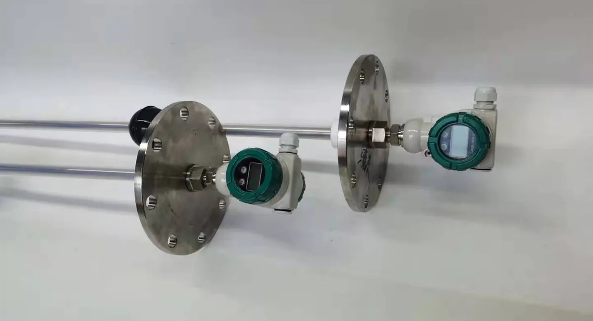
Comprehensive Technical Analysis and Industry Application Guide for Float Level Gauges
As one of the oldest and most reliable level measurement technologies in the industrial sector, the Float Level Gauge has undergone a massive evolution—from simple mechanical buoyancy principles to modern digitized, intelligent systems. Below is an in-depth analysis of this technology across its core dimensions:
1. Working Principle, Evolutionary History, and Engineering Logic
The core operation of a float level gauge relies on Archimedes’ Principle: any object, wholly or partially immersed in a fluid, is buoyed up by a force equal to the weight of the fluid displaced by the object. As the liquid level changes, the float rises or falls accordingly.
Its evolutionary history is a journey from “purely mechanical direct-viewing” to “remote electrical signal transmission,” and finally to “high-precision, non-contact wave propagation”:
Evolutionary Phases
Phase 1: Mechanical Indicator / Magnetic Flip-Column (The Primitive Era)
Process: Early designs utilized ropes, chains, or mechanical linkages to connect the float to an external pointer or counterweight. This later evolved into the Magnetic Level Indicator (MLI), where a permanent magnet assembly is sealed inside the float, driving external red-and-white magnetic rollers to rotate via magnetic coupling.
Engineering Logic: Hermetic containment is critical to prevent leaks. Purely mechanical linkages must penetrate the vessel wall, making them highly prone to fugitive emissions and packing leaks in high-pressure, toxic, or flammable media. Magnetic coupling technology achieved complete isolation between the process and the atmosphere, solving the seal integrity dilemma.
Phase 2: Reed Switch Chain (Resistance-Based Transmission)
Process: A dense array of reed switches and precision resistors are arranged inside a sealed guide stem. As the magnetic float moves up and down, it sequentially closes the corresponding reed switches, varying the total loop resistance. This resistance variation is then converted by an internal transmitter into a standard $4\sim20\text{ mA}$ analog signal.
Engineering Logic: With the rise of industrial automation (Industry 2.0/3.0), control rooms required remote level data. Purely visual magnetic flip-columns could not facilitate automated loop control, driving the evolution toward electrical output.
Phase 3: Magnetostrictive Technology (The Pinnacle of Modern Precision)
Process: The electronics head sends a low-current interrogation pulse down a magnetostrictive waveguide wire, creating a circular magnetic field. When this field intersects the magnetic field of the float, a torsional strain wave (Wiedemann Effect) is generated and propagates back up the waveguide. The absolute level is calculated by measuring the precise time-of-flight (ToF) of the wave.
Engineering Logic: Reed switch chains suffer from a “step-like” discrete error (where resolution is limited by reed switch density, typically $5\sim10\text{ mm}$) and mechanical contact fatigue. To satisfy the demands of oil, gas, and petrochemical refining for millimeter/micrometer-level accuracy and an ultra-long service life, magnetostrictive technology was developed.
2. Deep Dive into Core Technologies
Modern premium-tier float level gauges (represented by magnetostrictive and high-reliability magnetic coupling systems) rely on three foundational core technologies:
Core Technology I: Magnetostrictive Time-of-Flight (ToF) Chronometry
Technical Analysis: The propagation velocity of the ultrasonic strain wave along the waveguide wire is highly constant (approximately $3000\text{ m/s}$, with temperature-induced drifts compensated via proprietary algorithms). The microprocessor utilizes an ultra-high-frequency clock (picosecond-level timer) to measure the exact time interval $t$ between the emission of the interrogation pulse and the return of the return wave. Using the fundamental equation $S = v \times \frac{t}{2}$, the system resolves absolute position. The proprietary know-how lies in the metallurgical uniformity of the waveguide wire and the advanced signal filtering/capturing electronics.
Core Technology II: High-Pressure / Cryogenic Titanium Alloy and 316L Precision Welding
Technical Analysis: The float must withstand extreme external process pressures while maintaining a low bulk density to float freely on low-density liquids (such as liquefied petroleum gases or cryogenics). This demands an ultra-thin float wall combined with high structural yield strength. The core technology involves plasma arc or electron beam welding (EBW) to guarantee that the float will not deform, leak, or suffer from heat-affected zone (HAZ) cracking under extreme pressures exceeding $4.0\text{ MPa}$ or deep cryogenic temperatures down to $-196^\circ\text{C}$.
Core Technology III: High-Temperature Metallurgy & Anti-Demagnetization
Technical Analysis: Both magnetic level indicators and magnetostrictive transmitters depend entirely on the permanent magnets (typically Neodymium Iron Boron [NdFeB] or Samarium Cobalt [SmCo]) encapsulated within the float. In high-temperature applications (such as $300^\circ\text{C}\sim450^\circ\text{C}$ processes), magnetic materials are highly susceptible to thermal demagnetization, causing catastrophic device failure. The core technology lies in advanced magnetic stabilization heat treatment and thermal-barrier structural designs, ensuring that the magnetic flux degradation rate remains under 1% over years of continuous high-temperature service.
🛠️ Extended Technology Application Case Study (I): Digital Upgrades for Testing and Calibration Systems
As core float level measurement technologies have advanced, traditional calibration methods (which rely heavily on precision calipers and manual wire measurement) have failed to meet modern high-precision industrial standards due to excessive manual intervention and low automation levels.
The paper “Reverse Metrological Approach to the Mechanical Structural Design for Developing a New Generation of Fully Automatic Float Level Gauge Calibration Devices“ (published in Measurement Science Review, authored by researchers from the University of Žilina, Slovakia, etc.) addresses this gap for large fuel storage tanks. The research team developed a brand-new, fully automated verification and calibration reference device.
Hardware Upgrade: The system integrates an Incremental Optical Encoder equipped with a precision graduated dial and a specialized rewind pulley mechanism. This setup successfully converts the vertical linear displacement of the float into an angular rotation of the encoder, achieving high-precision, continuous digital calibration. The system is currently in its Test Operation phase.
3. Industrial Applications and Problem Solving
| Industry Sector | Specific Process Pain Point | How Core Technology Solves the Problem |
| Petroleum & Gas / Tank Farms | 1. The presence of oil and water simultaneously inside a single storage tank requires accurate tracking of the oil-water interface.
2. Flammable and explosive vapor spaces demand absolute explosion protection. | Dual-Float Magnetostrictive Technology: Employs two distinct floats calibrated to different specific gravities (one floating on the oil surface, the other sinking through the oil to float on the water interface) on a single stem. It resolves total level and interface simultaneously down to $\pm1\text{ mm}$, backed by Intrinsically Safe (Ex ia) global certifications. |
| Coal-to-Chemicals & High-Pressure Boilers | 1. Saturated steam boilers exhibit extreme high-temperature and high-pressure dynamics ($>200^\circ\text{C}$, $>6.0\text{ MPa}$).
2. Non-contact instruments like Radar suffer from signal attenuation due to steam condensation and gas-phase density fluctuations. | High-Pressure MLI / Magnetostrictive Combination: Pure physical buoyancy is entirely immune to gas-phase dielectric and density fluctuations. Coupled with high-temperature SmCo magnets, it provides consistent absolute position feedback under violent process turbulence, preventing boiler dry-burning or overfill disasters. |
| Fine Chemicals & Acid/Base Storage | 1. Highly aggressive media (concentrated $\text{H}_2\text{SO}_4$, $\text{HCl}$, $\text{HF}$) rapidly corrode metallic process connections and wetted parts.
2. High vapor volatility creates severe environmental and safety leakage risks. | Fluoropolymer (PTFE/PVDF) Lining and Encapsulation: The entire float and guide stem are completely encapsulated in heavy-wall fluoropolymers, isolating the internal magnetic components from the corrosive media. This ensures zero leakage and extends the instrument’s operational lifespan in severe corrosive applications. |
🏭 Extended Technology Application Case Study (II): Automated Safety Retrofits in Traditional Metals Processing
Beyond large-scale chemical complexes, float level technology plays an essential role in driving safety and automation improvements in traditional manufacturing environments.
In actual steel industry applications, the paper “Design and Application of a Magnetic Float Level Gauge System for Automatic Control of Wastewater Pumps in Hydraulic Rooms“ (focused on the metal processing and steel industry) highlights a classic operational hazard: in the hydraulic basement of a steel coil production line, the drainage of hazardous wastewater sumps was entirely managed via manual pump operation. This led to frequent wastewater overflows onto the hydraulic room floor, creating slick walking surfaces, violating occupational health and safety (K3) protocols, and endangering operators.
Technical Solution: The system utilizes a Float Magnetic Level Gauge featuring high-strength Neodymium magnets embedded inside the float to trigger a series of Reed Switches along the length of the guide rod. Configured as a Voltage Divider network, the float movement translates into a continuous voltage change. A microcontroller processes this analog value to automatically cycle the heavy-duty drainage pumps via power relays. Concurrently, an HMI built via LabVIEW displays real-time wastewater levels in the central control room, allowing operators to monitor hazardous zones remotely and completely eliminating overflow risks.
4. Advanced Metrological Frameworks, Product Innovation, and Solutions
Advanced Metrological Framework: Multiphysics Sensing & Dynamic Density Compensation
Traditional float level calculations treat the float as a static displacement component, assuming process fluid density remains constant. However, in real-world industrial environments, temperature swings cause fluid density to fluctuate, which directly alters the immersion depth of the float, creating a systemic measurement error. Furthermore, during historical product engineering phases, structural mechanics were often designed in isolation from metrological science, failing to analyze the holistic uncertainty of the system.
🔬 Advanced Metrological Framework Case Study (III): Reverse Metrological Engineering
Leading academic circles now advocate for a paradigm shift termed “Reverse Metrological Design,” which follows a rigorous engineering loop:
[Critical Element Analysis] ➔ [Mathematical Modeling of Measurement Uncertainty] ➔ [Derivation of Mechanical Manufacturing Tolerances and Material Selection].This advanced methodology is detailed in the previously cited paper “Reverse Metrological Approach to the Mechanical Structural Design for Developing a New Generation of Fully Automatic Float Level Gauge Calibration Devices” (Measurement Science Review). The authors demonstrate that skipping metrological modeling in the pre-construction phase allows critical error sources—such as geometric imperfections of the rewind pulley and thermal expansion coefficients—to be magnified by the encoder. By using uncertainty-driven design, engineers can calculate the exact manufacturing tolerances required for key components, embedding high-precision capability directly into the device’s structural DNA before it ever reaches the factory floor.
Product Innovation and Emerging Application Scenarios:
To overcome technical bottlenecks and satisfy niche environmental demands, industrial R&D teams have developed two highly distinct product paradigms:
Intelligent Dual-Waveguide Magnetostrictive Gauges with Dynamic Density Compensation: These devices fuse magnetostrictive time-of-flight theory with embedded multi-point temperature RTD arrays and pressure sensors, dynamically correcting the float’s immersion depth to eliminate “false level” errors caused by fluid density shifts.
Low-Cost Open-Source Hydrological Level Gauges: For field telemetry and remote tropical river monitoring where utility power is non-existent and commercial instruments are cost-prohibitive, technology has shifted toward rugged, low-cost minimalism.
🌿 Product Innovation Case Study (IV): Low-Cost Open-Source Float-Controlled Laser Level Gauges
The paper “Design and Implementation of a Low-Cost, Highly Autonomous Float-Controlled Self-Sustained Laser Level Gauge for Remote Tropical Environments“ (published in HardwareX, authored by Alain Pierret et al.) presents a unique cross-disciplinary fusion of traditional float mechanics and modern low-power laser telemetry.
The Problem Solved: Designed specifically for flash-flood monitoring in developing nations’ ungauged basins, this device circumvents expensive, fragile commercial encoders (such as the OTT-SE200) that rely heavily on grid power. The external mechanical shell is constructed entirely out of widely available PVC piping.
Operation & Performance: A lightweight internal float rises and falls vertically with the river stage, and an integrated low-power laser distance sensor measures the distance to the float target. Optimized low-power firmware allows the system to run autonomously for over 2 months on just 4 standard D-cell batteries. Maintenance crews can download data wirelessly via a smartphone Bluetooth terminal App without opening the weather-proof enclosure.
Field Validation: Following a rigorous full-rainy-season field deployment in a tropical rainforest stream (compiling $n = 8017$ high-frequency datapoints), this €220 open-source device demonstrated an extraordinary Mean Absolute Error (MAE) of just $2.6\text{ mm}$ compared to premium commercial instruments, proving that clever mechanical configuration can democratize industrial-grade hydrological monitoring.
5. Industrial Pain Points and Recommended Product Specifications
The table below summarizes typical industrial pain points along with recommended product architectures and engineering parameters:
| Target Industry / Deployment Scenario | Recommended Product Architecture | Critical Engineering Parameters | Operational Value Delivered |
| Retail Fuel Stations / Refinery Tank Farms | High-Precision Dual-Float Magnetostrictive Level Transmitter | * Measuring Range: $0.5 \sim 6\text{ m}$
* Accuracy: $\pm0.5\text{ mm}$ or $0.01\%\text{ FS}$
* Protocols: Modbus RTU / HART
* Capabilities: Simultaneous Level + Interface + 5-point Temperature | Meets custody-transfer accuracy requirements; multi-variable output reduces overall instrumentation costs per tank. |
| Power Plant Boilers / High-Pressure Autoclaves | Heavy-Wall High-Pressure MLI with Magnetostrictive Redundancy | * Design Pressure: $\le 26.0\text{ MPa}$
* Process Temp: $-196^\circ\text{C} \sim 450^\circ\text{C}$
* Fluid Density: $\ge 0.4\text{ g/cm}^3$
* Explosion Proof: Ex d IIC T6 Gb | Provides both clear local visual indication and electronic feedback loop redundancy; engineered against blowouts or thermal demagnetization under extreme pressures. |
| Semiconductor Wet Benches / Highly Corrosive Chemical Storage | Fluoropolymer-Encapsulated Corrosive-Service Level Gauge | * Wetted Materials: Solid PTFE / PP / PVDF / 316L with PTFE Liner
* Range: $\le 4\text{ m}$
* Ingress Rating: IP67 / IP68
* Operating Pressure: $\le 1.6\text{ MPa}$ | Complete chemical resistance against aggressive acids and bases, extending the Mean Time Between Failures (MTBF) to over 5 years without maintenance. |
6. Future Trends in the Industry 4.0 and Artificial Intelligence Era
In the era of Industry 4.0, the Industrial Internet of Things (IIoT), and Artificial Intelligence, the float level gauge is rapidly transforming from a passive mechanical component into an intelligent edge computing node:
1. Advanced Edge Connectivity via Ethernet-APL
Traditional $4\sim20\text{ mA}$ analog current loops are bottlenecked, transmitting only a single process variable. Future-ready smart float level gauges are moving toward Ethernet-APL (Advanced Physical Layer), OPC UA, and HART 7 topologies.
The Paradigm Shift: The level transmitter no longer just broadcasts a level percentage; it streams a rich dataset including internal electronics temperature, magnetic flux degradation metrics, and raw acoustic wave diagnostics back to the plant’s distributed control system (DCS). This allows seamless, high-bandwidth integration, as seen in the automated steel mill wastewater control architecture mentioned earlier.
2. AI-Driven Predictive Maintenance and Digital Twin Modeling
Historically, float level gauges have faced two operational vulnerabilities: “Mechanical Jamming” (due to process crystallization, scaling, or particulate buildup on the guide stem) and “Float Breach” (where fluid penetrates the float, causing it to sink).
The AI Advantage: By embedding localized AI microprocessors or routing telemetry to cloud-based machine learning models, modern gauges continuously perform Waveform Analysis on the returned magnetostrictive strain wave. If the algorithm detects signature wave-attenuation profiles or energy-damping tails, the AI can alert operators: “Guide stem scaling detected; mechanical jamming predicted within 15 days” or “Float mass variance detected; probable micro-fracture leak.”
Industrial Value: This shifts plant operations from reactive maintenance to true predictive maintenance, preventing catastrophic fluid spills, process upsets, or tank overfills.
3. Ultra-Low-Power Wireless Networks (LoRaWAN / NB-IoT) and Energy Harvesting
For highly distributed Industry 4.0 deployments—such as cross-country pipelines, remote hydrological catchments, or off-grid wellheads—trenching signal and power cables is financially prohibitive.
The Future: Combining ultra-low-power magnetostrictive circuit designs with integrated lithium thionyl chloride batteries, micro-solar harvesting, or thermal energy harvesters, future float level gauges will communicate natively over LoRaWAN, NB-IoT, or WirelessHART. Operating in micro-ampere sleep states and waking up only to transmit data on a scheduled interval or upon an anomalous level delta, these systems deliver true “plug-and-play” asset tracking for completely autonomous, unmanned facilities.
What is the primary difference between a magnetostrictive float-type level meter and a standard reed switch float-type level meter?
The primary difference lies in measurement resolution and lifespan. Reed switch gauges offer discrete, “step-like” measurements because their resolution depends on the physical spacing of the switches (typically $5\sim10\text{ mm}$), and their mechanical contacts are prone to fatigue. In contrast, magnetostrictive gauges use time-of-flight wave propagation along a waveguide wire to achieve continuous millimeter or even micrometer-level resolution (up to $\pm0.5\text{ mm}$) with zero mechanical wear and an exceptionally long service life.
How is a float-type level gauge affected when the density (specific gravity) of the process medium changes?
According to Archimedes’ principle, if the fluid density decreases, the float must sink deeper into the liquid to displace enough mass to equal its own weight, causing the gauge to read lower than the actual level. Conversely, a higher density results in a higher reading. In Industry 4.0 applications, this is resolved via dynamic software compensation using embedded temperature/pressure sensors or an extra fixed calibration float to calculate live density.
Why do magnetic flap level gauges sometimes exhibit "disordered flap colors" or jamming during commissioning or operation?
This typically happens for three reasons: first, the process valve was opened too rapidly during startup, causing the float to surge violently and scramble the magnetic rollers; second, the medium contains ferromagnetic impurities (such as iron filings) that adhere to the float, distorting the magnetic field or causing physical jamming; third, the process temperature exceeded the Curie point of the magnet, causing permanent demagnetization.
How can the safety and service life of a float-type level gauge be ensured in highly corrosive media (such as hydrofluoric acid or concentrated hydrochloric acid)?
The instrument must be fully protected using fluoropolymers (such as PTFE or PVDF). The standard engineering practice involves tightly lining a 316L stainless steel guide stem with a heavy-wall PTFE sleeve and utilizing a pure PVDF or PTFE float. Through magnetic coupling, all electronic components and metallic elements are completely isolated inside the anti-corrosive barrier, ensuring zero leakage.
Why is a float-type level gauge more stable than Guided Wave Radar (GWR) in saturated steam boilers or under operating conditions involving violent gas-liquid two-phase fluctuations?
Guided Wave Radar (GWR) relies heavily on the dielectric constant (Dk) of the medium. In high-pressure steam boilers, the dense vapor space alters the velocity of the radar wave, and condensation on the probe can cause false reflections. A float level gauge relies strictly on physical buoyancy. As long as the float’s density is correctly engineered, it remains entirely immune to gas-phase heavy vapors, steam condensation, or electromagnetic interference.
In the era of Industry 4.0, how can we prevent "false level" safety incidents caused by media crystallization in float-type level meters?
Industry 4.0 addresses this through AI-based predictive maintenance. Intelligent magnetostrictive transmitters do not just output a variable; they continuously stream raw return-wave graphics. When process crystallization or scaling begins on the stem, the wave’s energy and damping characteristics shift. Edge-computing AI algorithms detect these subtle waveform distortions and trigger an early warning before the float completely jams.
Why Trust Instrava?
We select manufacturers from a neutral, impartial standpoint, always with your best interests in mind.
Our very existence depends on helping you source the products that are the perfect fit for your needs.
Based in China, we are able to conduct on-site inspections of production environments and product quality firsthand.
We help you avoid intermediaries posing as factories.
We facilitate smoother after-sales support, eliminating time zone issues and the delays often associated with dealing directly with factories.
Our multilingual team ensures effective communication.
For a trading startup, every interaction with a client is a precious opportunity—a sign that you are willing to place your trust in us and give us the chance to prove ourselves.
In the digital age, while information is easily accessible, misconceptions often cloud the trust between people.
Instrava relies entirely on trust; it is our core philosophy and the foundation of our existence in society. It is the fundamental basis for our long-term growth and our commitment to serving the community.
Please place your trust in us.