
Home » Technology » Understanding Capacitive and RF Admittance Level Measurement: From Physical Principles to Industrial Application
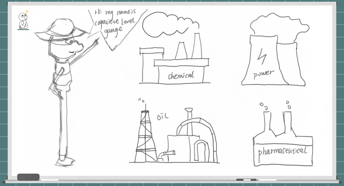
Understanding Capacitive and RF Admittance Level Measurement: From Physical Principles to Industrial Application
Introduction
In the era of industrial automation and Industry 4.0, high-precision liquid and bulk solid level measurement is a cornerstone of process control, operational safety, and quality traceability. As a classic yet continually evolving pillar of the level instrumentation family, capacitive and RF Admittance technologies break through the physical limitations of traditional mechanical or optical sensors.
This technical white paper delivers a deep dive into the four core technologies powering these sensors and provides a quantitative guide to selecting the right configurations for challenging industrial environments.
1. Deep Dive: The 4 Core Technologies
Technology 1: Dielectric Constant Disparity — The Fundamental Electrical Scale
Physical Formula: Governed by the classic parallel-plate capacitor equation:
$$C = \varepsilon \frac{A}{d}$$
- C = capacitance
ε = dielectric permittivity
A = electrode area
d = distance between electrodes Working Mechanism: The sensor probe (acting as the center electrode) and the conductive vessel wall (or a reference ground tube) form the two plates of a capacitor. As the liquid level rises or falls, the ratio of the media between the plates—changing from air/vapor to the target liquid—shifts.
Core Characteristic: Because the dielectric constant ($\varepsilon$) of most liquids (e.g., water $\varepsilon \approx 80$) is significantly greater than that of air ($\varepsilon \approx 1$), an increase in the liquid level leads to a proportional surge in total capacitance ($C$). By measuring this change, the transmitter calculates the continuous level with high linearity.
Technology 2: RF Admittance (Radio Frequency Admittance) — The Ultimate Answer to Build-up
Physical Formula: Admittance ($Y$) is the reciprocal of impedance ($Z$):
$$Y = \frac{1}{Z} = G + jB$$(Where $G$ represents the conductive/resistive component, and $B$ represents the susceptive/capacitive component).
Working Mechanism: Unlike traditional capacitance probes that only measure pure capacitance, RF Admittance measures both capacitance (imaginary part) and resistance (real part) simultaneously by applying a high-frequency, low-voltage RF signal to the probe.
Anti-Coating Core: Utilizing a unique 3-terminal or 5-terminal probe design, an active shield (driven shield) electrode is inserted between the active measuring element and the ground connection. By driving the active shield at the exact same frequency, phase, and potential as the measuring element, the voltage drop between them is forced to zero ($\Delta V = 0$). This cuts off the current flowing through any coating or material build-up to the vessel wall. The transmitter’s electronics perform synchronous rectification to separate the resistive current of the build-up from the capacitive current of the actual level, completely eliminating false readings.
Technology 3: Non-Contact Penetration Sensing — Fringing Electric Field Induction
Working Mechanism: The sensor does not come into direct contact with the process liquid. Instead, it is mounted externally to the outer wall of a non-metallic vessel or pipe (such as plastic, glass, or ceramic).
Core Characteristic: It leverages the “fringing electric field effect” to penetrate non-conductive barriers. When the liquid level reaches the installation height of the sensor, the high-dielectric liquid enters the localized electric field, altering the distributed capacitance between the external electrodes and the ground. This method achieves true zero-contamination and zero-leakage tracking.
Technology 4: Intelligent Dynamic Compensation & Multi-Point Calibration — The Algorithmic Brain
Temperature & Media Compensation: The dielectric constant of a liquid inherently drifts with temperature fluctuations. Modern smart transmitters feature embedded temperature sensing elements and compensation algorithms to correct these thermal measurement errors in real time.
Adaptive Calibration: Driven by onboard microprocessors (MCUs), users can perform empty-tank and full-tank calibration via a single click. The smart system automatically maps the baseline capacitance profile of the vessel, drastically reducing commissioning times.
2. Overcoming Harsh Process Bottlenecks
These four core technologies drive specific measurement strategies that directly address severe pain points across multiple process industries.
1. Eliminating Mechanical Wear and Leakage in High-Pressure Vessels
Target Processes: High-pressure boiler steam drums, liquefied gas tanks, high-pressure chemical reactors.
Traditional Bottlenecks: Mechanical instruments like float switches or magnetic level gauges rely on moving components. Under high pressure, vacuum cycles, or severe vibrations, floats are prone to crushing, jamming, or sticking. Furthermore, the dynamic seals at mechanical throughput points degrade over time, creating catastrophic media leakage hazards.
The Capacitive Solution: Based on Technology 1, the sensor is engineered as a solid-state metal rod or heavy-duty cable completely free of moving parts. Process connection integrity is maintained via a hermetic static seal (such as ceramic-to-metal firing). Because the capacitance shift is caused entirely by the passive rise of the media, mechanical jamming is impossible.
The Result: False levels due to stuck mechanical parts are entirely eliminated, and process containment risks under extreme pressure are reduced to near zero.
2. Solving Interface Measurement in Turbid or Equal-Density Liquids
Target Processes: Oilfield dehydration tanks, oil-water separators in petrochemical plants, industrial wastewater settling basins.
Traditional Bottlenecks: Measuring the interface between an upper layer of non-conductive organic material (oil) and a lower layer of conductive liquid (water) is a notorious challenge. When their densities are nearly identical or the tank contents become highly turbid due to agitation, buoyancy-based, ultrasonic, and optical sensors quickly fail.
The Capacitive Solution: While physical densities may match, water ($\varepsilon \approx 80$) and oil ($\varepsilon \approx 2$) sit on opposite sides of a vast dielectric chasm. When a continuous capacitance probe spans both layers, the section submerged in water contributes a capacitance value dozens of times higher than the section in the oil layer. As the interface rises (more water, less oil), the total capacitance registers a highly sensitive, sharp, differential leap.
The Result: No matter how turbid or opaque the emulsion layer becomes, as long as the chemical nature of the oil and water remains distinct, the capacitive probe instantly locks onto the exact interface line.
3. Defeating Media Build-up and False Alarms in Viscous Applications
Target Processes: Asphalt/bitumen storage tanks, heavy crude oil sumps, municipal sludge thickeners, chemical latex reactors.
Traditional Bottlenecks: Viscous, sticky, or crystallizing media leaves a heavy residue layer on the sensor probe when the level drops. Traditional capacitance switches, which only look at total capacitance, cannot differentiate between this “probe coating” and the “true liquid level.” This leads to locked “high-level” false alarms, resulting in severe dry-run damages or tank overfills.
The RF Admittance Solution: Powered by Technology 2, the active shield neutralizes the coating layer. Because there is no voltage differential between the measuring element and the shield极, no current passes through the coating on the probe body. The current from the transmitter’s measuring core can only flow through the actual process liquid to the tank wall.
The Result: The sensor “sees through” heavy coatings, triggering a response only when the real liquid surface physically contacts or clears the probe tip, neutralizing false alarms.
4. Mitigating Corrosive and Ultra-Pure Fluid Contamination
Target Processes: Semiconductor wafer etching baths (mixed acids/alkalis), biopharmaceutical bioreactors, medical IV/blood microfluidic loops, high-end consumer appliances.
Traditional Bottlenecks:
Instrument Destruction: Aggressive chemical agents (e.g., hydrofluoric acid) quickly dissolve bare metal probes.
Process Contamination: In ultra-pure pharma and semiconductor lines, even trace metallic ion leaching or bacterial breeding on submersed probes will scrap an entire batch.
Form Factor Constraints: Microfluidic devices and smart appliances have zero spatial tolerance for bulky internal sensors.
The Non-Contact Solution: Capitalizing on Technology 3, flexible capacitive sensor arrays or point patches are adhered directly to the exterior of non-metallic (plastic, quartz, glass) walls. The sensor projects an electric field through the container wall to monitor internal level shifts.
The Result: A permanent physical barrier stands between the sensor and the fluid. The medium cannot corrode the sensor, and the sensor cannot contaminate the medium. The ultra-thin footprint ensures seamless integration into compact enclosures.
3. Industrial Selection & Engineering Specification Guide
To translate theory into field-ready success, engineers must match the sensor’s physical configuration and electrical sensitivity to the specific process parameters.
Engineering Specification Matrix by Application
1. Corrosive & Ultra-Pure Fluids (Semiconductor, Fine Chemical, Pharma)
Typical Media: Hydrofluoric acid, hydrochloric acid, deionized water, sterile pharmaceutical solutions.
Critical Selection Parameters:
Probe Insulation/Wetted Material: Must specify a continuous, pinhole-free PTFE, PFA, or PEEK encapsulation. No metal-to-medium contact is permitted.
Dielectric Range: Compatible with $\varepsilon \ge 1.8$. For high-permittivity liquids like DI water ($\varepsilon \approx 80$), the transmitter must feature a high-range capacitance attenuation circuit to prevent signal saturation.
Process Limits: Typically atmospheric up to $1.6 \text{ MPa}$; temperature range $-40^\circ\text{C}$ to $+120^\circ\text{C}$.
Process Connection: Solid PTFE threads or fluoropolymer-faced flanges for 100% chemical inertness.
2. High-Viscosity, Crystallizing & Coating Media (Sludge, Bitumen, Adhesives)
Typical Media: Hot asphalt, vacuum distillation residues, heavy sludge, paper pulp, industrial glues.
Critical Selection Parameters:
Measurement Principle: Mandate RF Admittance with an active, driven shield.
Active Shield Length: Must be tailored to the vessel’s mounting nozzle. The shield length must be $\ge$ the total nozzle height + 50 mm to ensure the stagnant residue zone inside the nozzle is completely ignored.
Temperature Rating: High-temperature applications (e.g., bitumen) require probe assemblies rated for $+230^\circ\text{C}$ to $+400^\circ\text{C}$, paired with a cooling neck or remote-mounted electronics.
Electrical Sensitivity: Minimum resolution $\le 0.5 \text{ pF}$ with a phase-separation algorithm capable of compensating for conductive coating resistance down to $500 \ \Omega$.
3. High-Temperature, High-Pressure, & Critical Safety Processes (Power, Petrochemical)
Typical Media: Saturated steam boiler drums (boiler feedwater), Liquefied Natural Gas (LNG), high-pressure liquid ammonia.
Critical Selection Parameters:
Probe Seal Engineering: Must utilize a Ceramic-to-Metal Fired/Sintered Seal as the primary pressure boundary, backed by dual-layer heavy-duty packing glands.
Pressure & Temperature Ratings: Nominal pressure ratings up to $6.3 \text{ MPa}$ to $32 \text{ MPa}$; temperature survival from $-200^\circ\text{C}$ (Cryogenic LNG) up to $+500^\circ\text{C}$.
Probe Geometry: For continuous measurement under turbulent, high-pressure flows, select a solid, heavy-gauge $\phi 12 \text{ mm}$ to $\phi 20 \text{ mm}$ stainless steel (316L or Hastelloy) rod probe rather than a cable probe to eliminate whip damage.
Hazardous Area Certification: Intrinsic Safety (Ex ia IIC T6) or Flameproof/Explosion-Proof (Ex d IIC T6) global certifications are mandatory.
4. Miniature Form Factors & Non-Metallic Wall Adhesion (Medical, Smart Appliances)
Typical Media: Ophthalmic solutions, saline, blood, purified water, coffee extract.
Critical Selection Parameters:
Form Factor: External non-contact flexible capacitive strip or compact point sensors.
Barrier Limits: Non-metallic pipe/vessel wall thickness $\le 5 \text{ mm}$ for optimal field penetration. Compatible with pipe diameters from $3 \text{ mm}$ to $25 \text{ mm}$.
Capacitance Resolution: Because external sensing measures faint distributed capacitance fields, the sensor must deploy a high-resolution Capacitance-to-Digital Converter (CDC) chip (e.g., 24-bit resolution) with a minimum detection threshold of $\le 0.001 \text{ pF}$ ($1 \text{ fF}$).
Electrical Interface: Low-power consumption ($3.3\text{V}$ to $5\text{V}$ DC) with TTL, I2C, or Open Collector (OC) outputs for direct micro-controller integration.
4. Technical Mapping & Selection Prohibitions
1. Product Selection Decision Matrix
| Application Category | Preferred Technical Solution | Critical Engineering Parameters | Addressed Industrial Pain Point |
| Corrosive & Ultra-Pure Fluids | Contact Probe with Full Encapsulation Capacitor | • Insulation: Continuous PTFE / PFA / PEEK
• Permittivity: $\varepsilon \ge 1.8$
• Feature: High-range attenuation circuitry | Prevents metallic ion leaching into ultra-pure products and resists severe acid/alkali corrosion. |
| High-Viscosity & Heavy Coating | RF Admittance Switch / Transmitter | • Configuration: 3 or 5-terminal driven shield
• Shield Length: $\ge$ Mounting nozzle height + 50mm
| Eliminates false high-level alarms caused by viscous material build-up and sticky residue on the probe. |
| High-Temperature & High-Pressure | Solid-State Rigid Probe with Sintered Seal | • Sealing: Ceramic-to-metal fired seal
• Pressure Rating: Up to $32 \text{ MPa}$
• Probe Type: Heavy-gauge ($\phi 12 \sim \phi 20\text{mm}$) solid rod | Eradicates dynamic seal leakage and prevents mechanical float deformation or jamming under severe process turbulence. |
| Miniature & Non-Contact Channels | External Non-Contact CDC Sensor | • Resolution: High-sensitivity CDC $\le 1 \text{ fF}$ ($0.001 \text{ pF}$)
• Wall Limit: Non-metallic barrier thickness $\le 5\text{mm}$ | Overcomes extreme spatial constraints in microfluidic devices and guarantees zero cross-contamination. |
2. Selection Prohibitions & Boundaries
While capacitive and RF Admittance technologies provide robust and highly reliable answers to these complex problems, their physical foundation is inherently bound to the stability of the medium’s dielectric constant ($\varepsilon$).
⚠️ The Absolute Technology Prohibition:
Do NOT use capacitance or RF Admittance instrumentation for continuous level tracking in vessels that frequently rotate between entirely different media with highly disparate dielectric profiles (e.g., a batch storage tank holding Diesel Fuel $\varepsilon \approx 2.1$ on Monday, and shifting to Pure Ethanol $\varepsilon \approx 25$ on Tuesday). Without constant re-calibration, the transmitter will output highly erroneous data because it cannot differentiate between a change in liquid height and a change in the fluid’s molecular permittivity.
💡 The Instrava Engineering Recommendation:
For applications characterized by frequent media changeovers, or processes where chemical reactions cause the dielectric constant to drift unpredictably in real time, engineers should bypass capacitive principles. For these specific scenarios, specify 80GHz / 120GHz High-Frequency Non-Contact Radar Level Transmitters or Guided Wave Radar (GWR) to ensure true media-independent, maintenance-free operation.
What is the main difference between traditional capacitance level sensors and RF Admittance sensors?
Traditional capacitance sensors measure only pure capacitance, making them highly prone to false alarms when sticky media builds up on the probe. In contrast, RF Admittance technology measures both capacitance and resistance (admittance) simultaneously. By utilizing an active/driven shield, it cuts off current leakage through the residue and dynamically isolates the coating’s resistance from the actual liquid level, completely eliminating false readings in viscous applications.
Can capacitive level sensors measure the interface between two liquids, like oil and water?
Yes, through the Dielectric Constant Disparity method. Even if oil and water have nearly identical physical densities or are completely turbid, they possess vastly different dielectric constants (water $\varepsilon \approx 80$, oil $\varepsilon \approx 2$). A continuous capacitive probe detects the sharp change in electrical capacitance at the boundary layer, allowing it to instantly map the exact interface line.
How do non-contact capacitive level sensors work without touching the liquid?
These sensors rely on the fringing electric field effect. Compact or flexible capacitive sensor arrays are adhered directly to the outside of a non-metallic container or pipe (such as plastic, quartz, or glass). The sensor projects a high-frequency electric field through the wall. When the internal liquid rises to meet the sensor, its high permittivity alters the distributed capacitance outside the pipe, triggering an accurate level detection without any physical process contact.
What happens to a capacitive level sensor's accuracy when the temperature changes?
Because a liquid’s dielectric constant inherently shifts with temperature fluctuations, uncompensated sensors will suffer from severe thermal drift (measurement data “creeping” up or down). Modern smart transmitters solve this by integrating Intelligent Dynamic Compensation. They combine an embedded temperature element with real-time algorithms to mathematically nullify thermal drift before exporting the signal.
In what type of industrial application is a capacitive level sensor strictly prohibited?
Continuous capacitive level tracking is strictly prohibited in tanks that frequently rotate between entirely different chemical media with widely disparate dielectric constants (e.g., storing diesel $\varepsilon \approx 2.1$ one day and pure ethanol $\varepsilon \approx 25$ the next). Because the physical baseline of the sensor is bound to the chemical permittivity of the medium, switching fluids without manual recalibration will cause severe reading errors.
If my process features frequent media changeovers, what instrument should I use instead of a capacitive sensor?
For batch applications with constant fluid type changes or unstable chemical reactions where the dielectric profile drifts unpredictably, you should bypass capacitive technology entirely. The optimal alternative is to deploy an 80GHz / 120GHz High-Frequency Non-Contact Radar Level Transmitter or a Guided Wave Radar (GWR), both of which offer true media-independent, maintenance-free level tracking.
Why Trust Instrava?
We select manufacturers from a neutral, impartial standpoint, always with your best interests in mind.
Our very existence depends on helping you source the products that are the perfect fit for your needs.
Based in China, we are able to conduct on-site inspections of production environments and product quality firsthand.
We help you avoid intermediaries posing as factories.
We facilitate smoother after-sales support, eliminating time zone issues and the delays often associated with dealing directly with factories.
Our multilingual team ensures effective communication.
For a trading startup, every interaction with a client is a precious opportunity—a sign that you are willing to place your trust in us and give us the chance to prove ourselves.
In the digital age, while information is easily accessible, misconceptions often cloud the trust between people.
Instrava relies entirely on trust; it is our core philosophy and the foundation of our existence in society. It is the fundamental basis for our long-term growth and our commitment to serving the community.
Please place your trust in us.