
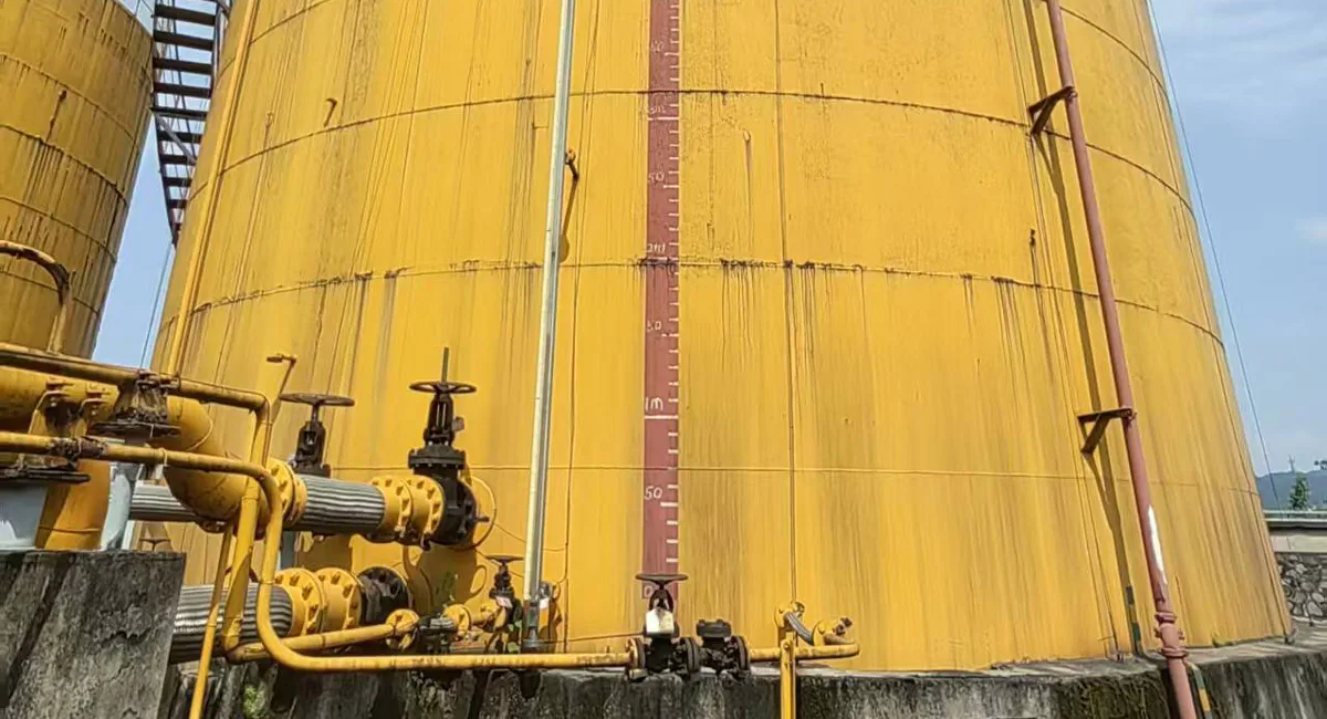
มาตรวัดระดับแม่เหล็ก: วิวัฒนาการทางเทคนิค หลักการพื้นฐาน และอนาคตในอุตสาหกรรม 4.0 และยุคปัญญาประดิษฐ์
As one of the most traditional yet highly reliable field-contact instruments in industrial process control, the Magnetic Level Gauge (MLG) plays a critical role in modern engineering. Below is an in-depth analysis of its working principles, technological evolution, core technologies, industry applications, and its transformation path toward Industry 4.0.
1. Working Principle, Evolution, and Drivers
Core Working Principle
The magnetic level gauge operates on two fundamental physics concepts: Archimedes’ Principle of Buoyancy ($F_b = \rho g V$) and the Principle of Magnetic Coupling.
External Structure: It primarily consists of a bypass chamber (measuring tube), a magnetic float, a local indicator (magnetic flaps/rollers), and an optional remote transmitter.
Operational Logic: As the liquid level in the vessel rises or falls, the level inside the bypass chamber shifts synchronously. The magnetic float inside the chamber moves up and down accordingly. A permanent magnet assembly inside the float creates a magnetic field that penetrates the non-magnetic chamber wall. This field magnetically couples with and rotates the dual-colored magnetic flaps in the external indicator by 180°. When the level rises, the flaps flip from white to red (or another contrasting color); when the level falls, they flip back to white, providing a clear, highly visible local reading of the liquid level.
[Process Vessel] <--> [Bypass Chamber (Float inside w/ Magnets)] ---> (Magnetic Field Wall Penetration) ---> [External Flag Indicator (Red/White)]
Technical Evolution and Drivers
The development of liquid level measurement has progressed from “direct visual contact” to “isolated safety,” and finally to “digitalized transmission”:
Glass Tube / Gauge Glass (Primitive Stage)
(Driver: Eliminate bursting and leakage risks under high pressure/toxic media) Mechanical Float / Heavy-Hammer Steel Tape (Transition Stage)
(Driver: Eliminate wear and tear of dynamic seals to achieve zero leakage) Magnetic Level Gauge (Modern Stage: Magnetic Coupling + Static Seal Isolation)
(Driver: Meet automation, remote monitoring, and safety interlocking demands) Smart Magnetic Level Gauge (Advanced Stage: Integrated Magnetostrictive / Radar Dual-Mode)
First Stage: Glass Tube / Gauge Glass (Direct Vision)
Defects: Glass has strictly limited temperature and pressure ratings. When exposed to corrosive, flammable, explosive, or highly toxic media, a sudden glass rupture could trigger catastrophic industrial accidents. Furthermore, scaling or fouling quickly renders the fluid level invisible.
Second Stage: Mechanical Float / Heavy-Hammer Gauges (Mechanical Transmission)
Defects: These systems rely on steel cables, linkages, or gears to transmit the level signal across the vessel wall. This requires dynamic seals (such as gland packings or rotating shafts), which inevitably wear down over time, causing product leaks.
Third Stage: Magnetic Level Gauge (Magnetic Coupling & Isolation)
Evolutionary Driver: Achieving “Zero Leakage” Absolute Safety. Engineers utilized non-magnetic metals (like stainless steel or exotic alloys) to completely isolate the process medium within a pressure-sealed bypass pipe. By leveraging magnetic fields that easily pass through non-magnetic barriers, signals are transmitted “wirelessly” to the outside. This static seal design completely eliminates fugitive emissions and leakage hazards caused by instrument failure.
2. Comprehensive Breakdown of Core Technologies
To perform flawlessly under extreme conditions—such as ultra-high temperatures, high pressures, low fluid densities, and severe corrosion—the magnetic level gauge relies on four pillar technologies:
① Magnetic Stability & High-Temperature Demagnetization Control
The heart of an MLG is the stability of its magnetic coupling.
การเลือกวัสดุ: High-grade permanent magnetic materials with exceptional remanence and coercivity, such as AlNiCo (Aluminum-Nickel-Cobalt) หรือ SmCo (Samarium-Cobalt), are utilized.
The Technology: Industrial processes (like power plant boiler drums) often reach temperatures between 300°C and 450°C. High heat naturally induces thermal demagnetization. Advanced MLGs utilize proprietary thermal stabilization pre-treatment on the magnets alongside highly optimized magnetic circuit designs. This guarantees the float maintains a strong magnetic field capable of penetrating thick, high-pressure chamber walls without suffering field decay or causing discontinuous flag flipping.
② High-Pressure, Lightweight Float Design & Fabrication
Floats face an engineering paradox: they must be heavy/strong enough to withstand crushing pressures, yet light/hollow enough to float in low-density liquids.
Structural Optimization: Engineers apply Finite Element Analysis (FEA) to optimize wall thickness and geometry (typically cylindrical bodies with elliptical or hemispherical end caps). High-strength materials like Titanium Grade 5 or specialized thin-walled stainless steels are preferred.
Welding Precision: Manufacturing relies on high-precision automated laser welding หรือ TIG (Tungsten Inert Gas) welding. Post-weld procedures require 100% X-ray radiographic testing and extreme external hydrostatic pressure testing to ensure the integrity of the seams under cyclic pressure stresses, preventing medium ingress that would cause the float to sink.
③ Precision Anti-Jamming Indicator Technology
The external flag indicator is exposed to harsh atmospheric conditions, including UV radiation, sandstorms, rain, and corrosive ambient gases.
Design Engineering: Flags are engineered from ceramics or aluminum alloys coated with high-temperature Teflon (PTFE). Internal guide shafts or pivot pins utilize self-lubricating structures or synthetic ruby bearings to prevent dust accumulation or oxidation from seizing up the mechanism.
Hermetic Sealing: High-end indicators feature vacuum glass encapsulation หรือ nitrogen-purged hermetic sealing to fully isolate internal components from moisture and ambient corrosive vapors, completely eliminating internal condensation and corrosion.
④ Magnetostrictive Dual-Mode Remote Transmission
To feed data directly into Distributed Control Systems (DCS), a remote transmitter is clamped along the side of the bypass chamber.
Technological Principle: As the magnetic float moves, its magnetic field interacts with an interrogation pulse sent down a magnetostrictive waveguide wire inside the transmitter tube. This creates a torsional wave that travels back to the pickup electronics. By calculating the precise time-of-flight, the system achieves micron-level accuracy (±1mm). Combining the local physical indicator with the high-precision electronic transmitter creates an invaluable safety redundancy.
3. Industrial Applications and Pain Points Solved
| ภาคอุตสาหกรรม | Process Node & Media | Core Industry Pain Points (Legacy Limitations) | Magnetic Level Gauge Solutions |
| Petrochemical / Oil & Gas | Alkylation units, LPG/LNG storage tanks, toxic hydrofluoric acid, liquid hydrocarbons, $H_2S$ (sour gas) media. | 1. Flammable, Explosive, & Toxic: Even micro-leakage can lead to fatal explosions or toxic clouds. 2. Low Density & High Pressure: Light hydrocarbons have extremely low densities ($\rho < 0.5\text{ g/cm}^3$), making standard mechanical buoyancy floats sink. | Fully sealed bypass chambers provide absolute static containment, eradicating leak paths. Custom titanium alloy ultra-light floats can effectively buoyancy-track fluids with densities as low as $0.4\text{ g/cm}^3$. |
| Coal & Fine Chemicals | Ammonia synthesis reactors, urea synthesis towers, strong acid/base intermediate tanks. | 1. Aggressive Corrosion: Highly corrosive media rapidly eat through metals, causing catastrophic wall thinning. 2. Crystallization & Viscosity: Media tend to crystallize, clogging the ports of radar cones or differential pressure transmitters. | The interior of the chamber can be seamlessly lined or extruded with thick PTFE/PFA coatings, and the float can be fully encapsulated in fluoropolymers. The wide-bore bypass chamber easily tolerates mild crystallization without clogging. |
| Power Generation (Fossil/Nuclear) | Boiler steam drums, high/low-pressure feed heaters, deaerator storage tanks. | 1. Ultra-high Temperature & Pressure: Saturated steam systems run up to tens of megapascals and hundreds of degrees Celsius, causing rapid glass erosion and shattering risks. 2. Violent Flashing & False Levels: Internal boiling creates severe turbulence. | Utilizes heavy-walled, high-pressure stainless steel chambers (withstanding up to 42MPa) paired with ultra-high-temperature AlNiCo magnets. The bypass chamber acts as a natural stilling well, dampening turbulent boiling to display a true, stable liquid level. |
4. Theoretical Upgrades and Next-Generation Product Development
Advanced Theoretical Foundations
Next-generation developments leverage “Magnetic Circuit Simulation Theory (based on Maxwell 3D Electromagnetic Analysis)” และ “Multi-Phase Fluid Dynamics Coupling Theory.” By accurately mapping the hydrodynamic resistance of the float in non-Newtonian or high-viscosity fluids, alongside modeling electromagnetic flux attenuation as metal chamber walls thicken, engineers can design optimal structural configurations before prototyping.
Resulting Next-Generation Products
1. Dual-Chamber Redundant “All-in-One” Level System (MLG + Guided Wave Radar)
Product Concept: Instead of a single bypass pipe, this system uses a dual-chamber interconnected manifold. One chamber houses the traditional magnetic float (driving the local flags and a magnetostrictive transmitter), while the adjacent parallel chamber is directly fitted with a Guided Wave Radar (GWR) level meter.
Process Vessel Connections-Chamber A: Float(Local Flaps + Mag Tx)
Process Vessel Connections-Chamber B: Radar(Direct Electromagnetic)
Problems Solved: This solves the critical vulnerability of “single-principle common-cause failure” within Safety Instrumented Systems (SIS) in chemical plants and boiler drum lines.
If the process fluid density changes drastically due to thermal spikes, causing the float to sink (buoyancy failure), the Guided Wave Radar will still track the level accurately via electromagnetic wave reflection.
If severe coating or a changing dielectric constant throws off the radar waves, the physical float and flaps continue to operate flawlessly.
This integrated design yields an architecture ready for SIL2 / SIL3 (Safety Integrity Level) loops with high hardware fault tolerance.
2. Self-Adaptive Density-Compensating Smart Magnetic Level Gauge
Product Concept: Features a micro-servo balancing mechanism embedded inside the float or combines an external chamber layout with multi-sensor differential pressure and temperature arrays.
Problems Solved: It completely eliminates measurement drift caused by changes in fluid density—a major issue in chemical batch reactors or liquefied gas storage where temperatures swing wildly—by executing automatic real-time software calibration.
5. Industrial Requirements & Technical Parameter Matrix
| Core Industry Pain Point | Recommended Level Gauge Type | Technical Parameter Specifications |
High pressure, highly lethal, flammable/explosive media (e.g., LNG, Hydrogen Sulfide) | High-Pressure Explosion-Proof MLG | ความดันตามชื่อ: Class 1500 / PN26.0 to PN42.0 MPaOperating Temp: -196°C to +200°Cความหนาแน่นปานกลาง: $\ge 0.45\text{ g/cm}^3$กันระเบิด: Ex d IIC T6 Gb / SIL2Primary Material: 316L / Titanium Alloy |
High-temp, high-pressure saturated steam loops (e.g., Boiler steam drums) | Ultra-High-Temperature & Pressure MLG | ความดันตามชื่อ: PN10.0 to PN25.0 MPaOperating Temp: +300°C to +450°C (Peaks to 520°C)ความหนาแน่นปานกลาง: $\ge 0.60\text{ g/cm}^3$Magnet Material: High-stability AlNiCo GradeRemote Output: 4-20mA + HART / Modbus |
Aggressive acids, alkalis, and chemical corrosives (e.g., Concentrated HCl, Hydrofluoric acid) | Corrosion-Proof Fluoropolymer Lined MLG | ความดันตามชื่อ: PN1.0 to PN4.0 MPaOperating Temp: -40°C to +180°CLining Material: PTFE / PFA / F46วัสดุลอยน้ำ: Titanium with PTFE shield / Pure PVDFช่วงการวัด: 0.3m to 6m |
Industrial SIS Safety Interlocking Loops (Demanding dual-redundancy) | Dual-Chamber MLG + Guided Wave Radar System | ความถูกต้อง: Local Flags ±10mm; Remote Radar ±2mmOutput Interface: Dual independent 4-20mA (HART) channelsSafety Rating: Independent 3rd-party certified SIL3 capableการป้องกันสิ่งแปลกปลอมและการกันน้ำ: Dual-certified IP66 / IP67 enclosure |
6. Development Trends in the Industry 4.0 and AI Era
In the wake of Industry 4.0, Digital Twins, and Industrial AI Big Models, the historically mechanical magnetic level gauge is undergoing a comprehensive digital transformation:
① Edge AI & Prognostics and Health Management (PHM)
Next-generation smart magnetic level gauges do more than just output a baseline raw level value. Their remote transmitter heads feature built-in ultra-low-power Edge AI microcontrollers.
Float Jamming & Scaling Diagnostics: The Edge AI algorithm continuously analyzes the time-domain waveform of the level changes. If it detects non-natural “step changes” (jerky, step-like data patterns), it diagnoses localized scaling or float sticking, flagging a Predictive Maintenance (PdM) alarm before the gauge completely freezes up.
Magnetic Decay Forecasting: By modeling historical temperature integration against real-time magnetic feedback, the AI calculates the float’s demagnetization curve. It determines the instrument’s Remaining Useful Life (RUL), shifting plant maintenance from rigid schedules to data-driven, condition-based operations.
② Industrial Internet of Things (IIoT) & Native Data Fusion
Adoption of Ethernet-APL (Advanced Physical Layer): Traditional, narrow-bandwidth 4-20mA loops will give way to Ethernet-APL. The magnetic level gauge will have its own unique IP address, delivering high-speed 10Mbit/s bandwidth to transmit multi-variable telemetry (level, temperature, multi-point pressure, and device vibration) directly to the enterprise cloud.
Infrastructure-Free Wireless Deployment (WirelessHART / 5G-RedCap): For highly isolated tank farms, smart MLGs integrated with micro-solar and energy-harvesting batteries enable true “out-of-the-box” wireless operations, bypassing the massive civil and material expenses of running cables across a facility.
③ Activating the Digital Twin
Within a 3D virtual plant control room, every physical magnetic level gauge has an identical 1比1 virtual replica.
Process variables like temperature, system pressure, and changing densities are continuously fed into fluid dynamic equations on the cloud. The AI model compares the live physical level readings with virtual theoretical values. This enables Soft Sensing calibration on the fly and allows the system to deduce internal fluid composition changes—such as identifying fluid stratification, emulsification, or flash gas cavitation—transforming a simple local viewport into a highly intelligent asset for the modern automated plant.
The display on the magnetic flap level gauge is inaccurate; what is the cause, and how should it be resolved?
Potential Causes:
1.Density Deviation: The actual density of the process medium has changed due to temperature or pressure shifts, causing the float’s immersion depth to alter from its original factory calibration.
2.Magnetic Weakening: The permanent magnets inside the float have undergone thermal demagnetization over long-term exposure to high temperatures.
3.Float Scaling/Fouling: Heavy particulate buildup or scaling on the float has increased its weight, causing it to sit lower in the liquid.
4.Internal Vaporization: The medium is flashing or boiling inside the bypass chamber, creating a false liquid level due to gas-liquid mixture density variations.
Recommended Solutions:
1.Density Calibration: Recalibrate the scale or recalculate the level output based on the actual operating density of the fluid.
2.Inspect/Replace Float: Extract the float to check its magnetic field strength. Replace the float if significant magnetic degradation is found.
3.System Flushing: Open the drain valve at the bottom of the chamber to flush out sediments, and clean the float body if necessary.
4.Process Stabilization: Install insulation jackets or cooling/heating traces to prevent the medium from vaporizing or boiling within the chamber.
The flaps on the magnetic flap level gauge are failing to flip; what is the cause, and how should it be resolved?
Potential Causes:
1.Float Demagnetization: The float has completely lost its magnetic properties or the internal magnets have shifted out of alignment.
2.Indicator Mechanical Jamming: Ambient dust, moisture, or corrosive fumes have entered the indicator housing, causing the axis of the flaps to oxidize or jam.
3.Improper Mounting Distance: The indicator housing has shifted too far away from the bypass chamber, preventing the magnetic field from coupling with the flaps.
4.Reversed Float Polarity: The float was installed upside down during maintenance, resulting in reversed magnetic poles that cannot actuate the flaps correctly.
Recommended Solutions:
1.Magnetic Check: Run an external test magnet along the outside of the chamber. If the flaps flip smoothly with the external magnet but not with the internal float, replace the float.
2.Clean or Replace Indicator: Clean the indicator assembly to remove dust and obstruction. For severe oxidation, replace the indicator with a hermetically sealed or glass-vacuum encapsulated model.
3.Adjust Positioning: Securely tighten the mounting brackets to ensure the indicator is as close to the bypass tube as possible.
4.Correct Float Orientation: Re-verify the float’s marking (usually “Top” or an arrow) and reinstall it facing the correct direction.
The magnetic flap level gauge is leaking; what is the cause, and how should it be resolved?
Potential Causes:
1.Gasket Degradation: Process flanges or the bottom drain flange gaskets have aged, corroded, or suffered thermal deformation.
2.Chamber Corrosion/Perforation: The process medium has corroded through the non-magnetic stainless steel or alloy chamber wall.
3.Weld Fatigue: High vibration or pressure cycles have caused stress cracks along the process connection welds.
Recommended Solutions:
1.Isolate and Vent: Immediately close the process isolation valves connecting the gauge to the main vessel, and safely vent/drain the fluid inside the chamber.
2.Replace Gaskets: Replace the damaged seals with new gaskets rated for the specific process temperature, pressure, and chemical compatibility (e.g., Graphite, PTFE, or Spiral Wound gaskets).
3.Chamber Repair or Replacement: If the chamber body is perforated or cracked along a weld, replace the entire gauge assembly. Field-welding code-stamped pressure vessels should only be done by certified technicians following strict plant safety regulations.
The local display on the magnetic flap level gauge appears normal, but the remote display is abnormal; what is the cause, and how should it be resolved?
Potential Causes:
1.Transmitter Misalignment: The external remote transmitter (e.g., magnetostrictive sensor or reed switch rod) has physically slipped or moved out of the float’s magnetic detection zone.
2.Signal Interference (EMI): The transmission cable is unshielded or routed too close to high-voltage power lines, introducing electromagnetic interference.
3.Wiring Faults: Corroded terminals, loose connections, or a broken wire loop between the transmitter and the DCS/PLC.
4.Power Supply Issue: The loop power supply voltage dropped below the minimum operating threshold (typically 12V to 24V DC).
5.Electronic Failure: Internal component failure within the transmitter’s circuitry.
Recommended Solutions:
1.Reposition Sensor: Ensure the remote transmitter is mounted tightly parallel to the chamber and correctly aligned with the local zero line.
2.Verify Power and Wiring: Check terminal connections with a multimeter. Ensure the loop voltage is stable and that shielded twisted-pair cables are properly grounded at one end.
3.Recalibrate Electronics: Perform a zero and span calibration on the transmitter using either the device buttons, a HART communicator, or software interfaces.
4.Component Replacement: If the local indicator tracks perfectly but the electronic output remains frozen or erratic after calibration, replace the transmitter module.
The float within the magnetic flap level gauge is stuck and unable to rise or fall normally; what is the cause, and how should it be resolved?
Potential Causes:
1.Crystallization and Scaling: The medium has crystallized, polymerized, or left high-viscosity residue on the inner wall of the chamber or the float surface.
2.Foreign Particulates: Welding slag, rust flakes, or process debris have wedged themselves between the float and the chamber wall.
3.Chamber Deformation: The bypass tube has bent or suffered mechanical impact, destroying its internal concentricity.
4.Float Collapse: Sudden overpressure or vacuum conditions have crushed the thin-walled hollow float, altering its shape and buoyancy.
Recommended Solutions:
1.Flush the Chamber: Isolate the gauge and run a compatible solvent or steam flush through the top vent/rinse plug down through the drain valve to dissolve crystals and wash out particles.
2.Inspect the Float: Remove the bottom flange and carefully slide out the float. Check for physical damage, dimples, or liquid entry inside the float body. If it is deformed or filled with fluid, replace it immediately.
3.Verify Chamber Tolerances: Check the straightness of the bypass tube. If it is deformed or dented, replace the chamber housing.
The flaps on the magnetic flap level gauge are fluctuating frequently; what is the cause, and how should it be resolved?
Potential Causes:
1.Violent Process Turbulence: Rapid filling, emptying, or internal agitation within the main vessel creates severe waves and liquid surging.
2.Medium Flashing/Boiling: Continuous bubbling and boiling underneath the float cause it to dance or bounce erratically within the chamber.
3.Pulsating Pressure: Connected pumps or compressors create rapid pressure waves through the process piping.
Recommended Solutions:
1.Throttling Valves: Slightly throttle the process isolation valves (if permissible by plant safety standards) to restrict the velocity of fluid moving into the chamber, acting as a hydraulic damper.
2.Install a Damping Device: Retrofit a damping spring or a stilling well option inside the chamber to reduce the kinetic impact of the liquid on the float.
3.Thermal Insulation: Add proper insulation or heat-tracing to stabilize internal temperatures, stopping any localized phase changes (boiling/flashing) inside the bypass tube.
ทำไมต้องไว้วางใจ Instrava?
เราคัดเลือกผู้ผลิตจากมุมมองที่เป็นกลางและไม่ลำเอียง โดยคำนึงถึงผลประโยชน์สูงสุดของคุณเสมอ.
การดำรงอยู่ของเราขึ้นอยู่กับความสามารถในการช่วยคุณหาผลิตภัณฑ์ที่ตรงกับความต้องการของคุณอย่างสมบูรณ์.
ตั้งอยู่ในประเทศจีน เราสามารถดำเนินการตรวจสอบสถานที่จริงของสภาพแวดล้อมการผลิตและคุณภาพของผลิตภัณฑ์ได้โดยตรง.
เราช่วยคุณหลีกเลี่ยงคนกลางที่แอบอ้างว่าเป็นโรงงาน.
เราอำนวยความสะดวกให้การสนับสนุนหลังการขายราบรื่นยิ่งขึ้น โดยขจัดปัญหาเรื่องเขตเวลาและลดความล่าช้าที่มักเกิดขึ้นจากการติดต่อกับโรงงานโดยตรง.
ทีมงานหลายภาษาของเราทำให้การสื่อสารมีประสิทธิภาพ.
สำหรับบริษัทสตาร์ทอัพในวงการเทรดดิ้ง การติดต่อสื่อสารทุกครั้งกับลูกค้าคือโอกาสอันมีค่า — เป็นสัญญาณที่แสดงว่าท่านพร้อมที่จะวางใจในเรา และให้โอกาสเราพิสูจน์ความสามารถของเรา.
ในยุคดิจิทัลนี้ แม้ข้อมูลจะเข้าถึงได้ง่าย แต่ความเข้าใจผิดมักทำให้ความเชื่อมั่นระหว่างผู้คนถูกบดบัง.
Instrava พึ่งพาความเชื่อมั่นอย่างเต็มที่; นี่คือปรัชญาหลักของเราและเป็นรากฐานของการดำรงอยู่ของเราในสังคม นี่คือพื้นฐานสำคัญสำหรับการเติบโตในระยะยาวของเรา และความมุ่งมั่นของเราในการให้บริการแก่ชุมชน.
กรุณาไว้วางใจในเรา.