مقياس المستوى
الصفحة الرئيسية » أدوات قياس المستوى
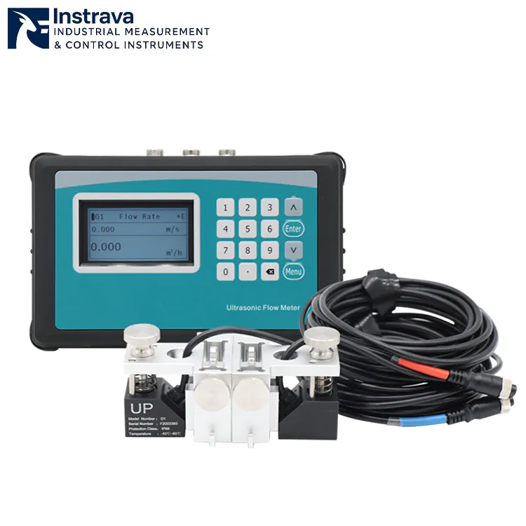
نطاق سرعة التدفق: ± 0.01 م/ث إلى ± 12 م/ث | حجم الأنبوب: 25 مم إلى 1200 مم (1 ″ إلى 48 ″)
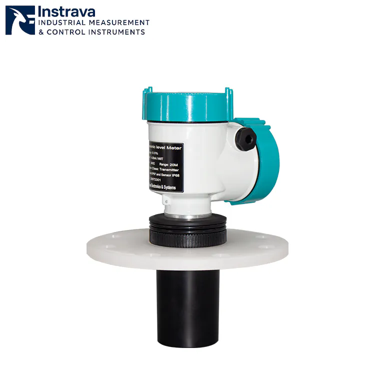
نطاق القياس: 4 م / 6 م / 8 م / 12 م / 20 م / 30 م
إشارة الخرج: 4-20 مللي أمبير (2 سلك)
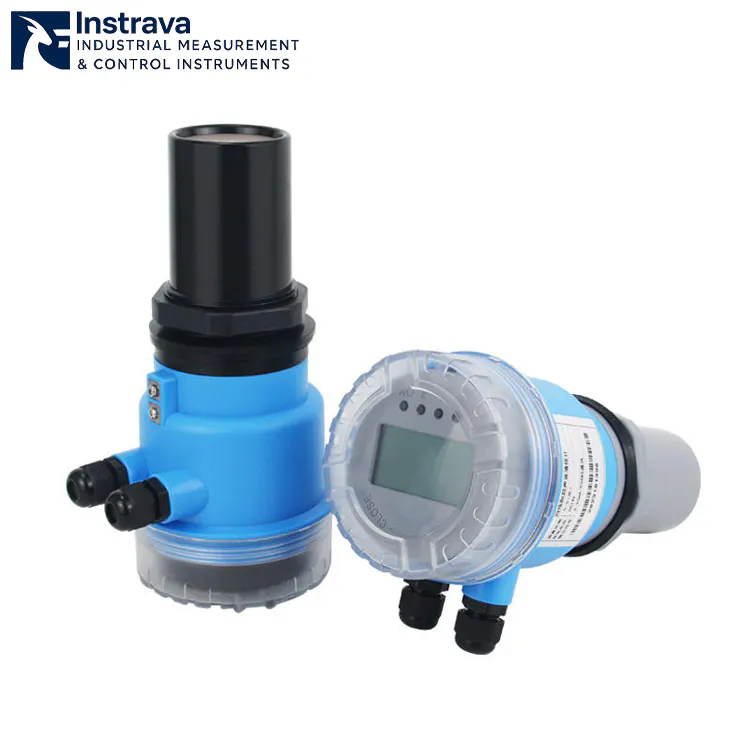
Wide measuring range (0–60m) | High accuracy (0.5%–1% FS)
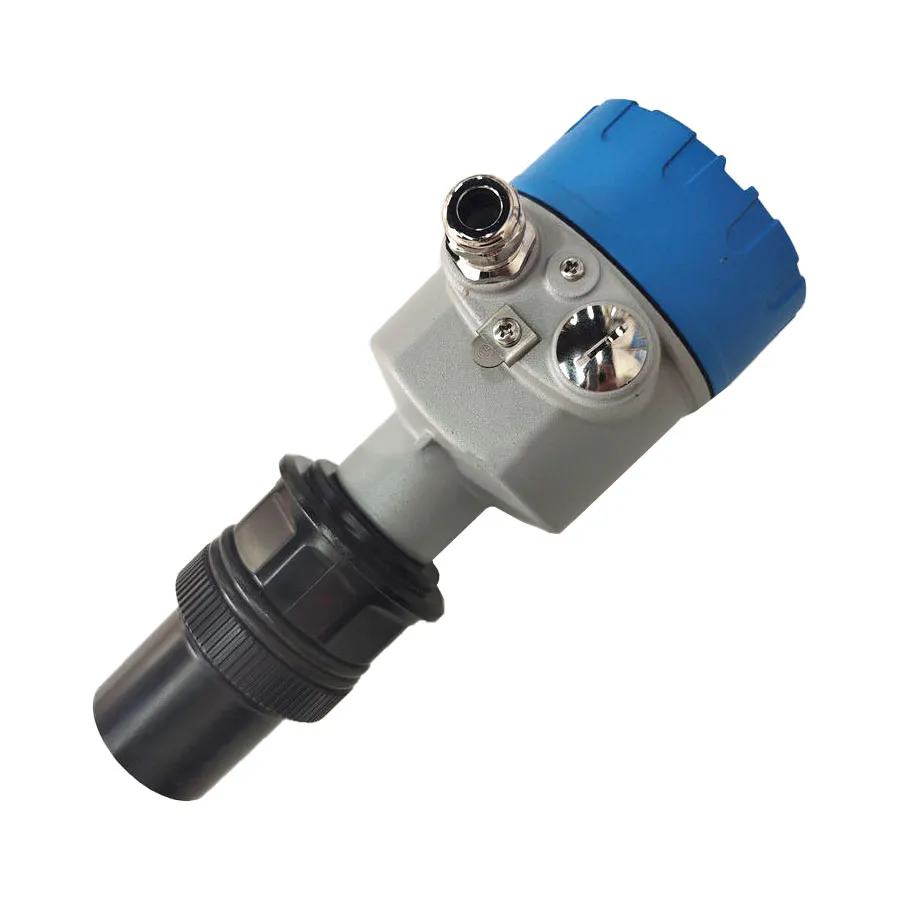
نطاق القياس: 0-60m
ضغط العمل: جهاز الصراف الآلي
Download liquid level gauge product information EN document
The level gauge can be used for level measurement of various industrial media such as water, oil, chemical liquids, corrosive media, high-viscosity liquids and slurries.
Level gauges are critical components in modern industrial automation systems designed to monitor and control the height of liquids, solids, or interfaces within tanks, silos, vessels, and pipelines. These instruments provide real‑time level data that help prevent overflow, dry‑run conditions, and process interruptions — ensuring safety, efficiency, and compliance across various applications.
في Instrava، نقدم مجموعة شاملة من أدوات القياس عالية الأداء المصممة هندسيًا لتحقيق الدقة والمتانة والاندماج السلس في أنظمة التحكم الصناعي.
What Is Level Gauge?
A مقياس المستوى (English: Level Gauge / Level Transmitter; Русский: Уровнемер; Español: Medidor de nivel; Français: Jauge de niveau) is an industrial instrument used to measure, monitor, and display the real-time height or volume of liquids, slurries, or granular solids inside a tank, vessel, or silo.
Acting as the “eyes” of industrial automation, it plays a critical role in process control, inventory management, and safety prevention across industries such as chemical processing, oil and gas, water treatment, and power generation.
Depending on the application, level gauges operate on various physical principles—ranging from simple visual indicators (like magnetic flaps) to advanced, non-contact electronic technologies like الرادار, الموجات فوق الصوتية, و Guided Wave Radar (GWR)—ensuring precise data transmission even under extreme conditions of high pressure, high temperature, or corrosive environments.
Common Types of Level Gauge
Industrial processes vary widely in media, conditions, and accuracy requirements. Below are the most widely used level gauges type:
1. Capacitive Level Gauge
Operates on the principle that the capacitance formed between the measuring probe and the vessel wall (or an auxiliary electrode) changes with the material level. Variations in the medium’s height alter the dielectric constant or the electrode coverage area, which is then converted into standard electrical signals.
✔ Zero Mechanical Wear: Compact structure with no moving parts, ensuring extremely low maintenance costs.
✔ High Pressure Resistance: Capable of operating stably under ultra-high pressure, high vacuum, or high-temperature environments.
✔ Versatile Applications: Highly suitable for measuring conductive/non-conductive liquids, highly corrosive media, and powders or granules.
2. Displacer Level Gauge
Based on Archimedes’ buoyancy principle. A displacer (internal cylinder) suspended from a spring or torque tube is immersed in the liquid. As the liquid level rises, the buoyant force on the displacer increases, reducing its apparent weight. The mechanical structure converts this weight change into a level signal.
✔ High-Precision Measurement: Exceptionally well-suited for measuring the interface between two liquids of different densities.
✔ Extreme Process Conditions: Exhibits excellent stability in large vessels under high temperatures, high pressures, and high vacuums.
✔ Turbulence Resistance: Compared to standard floats, the displacer provides superior suppression against turbulent surfaces or wave action.
3. Electrode Level Gauge (Conductivity Level Switch)
Utilizes the electrical conductivity of liquids to detect levels. When the liquid comes into contact with metal electrode rods of varying lengths, the electrical circuit closes, triggering a switch signal or controlling pump start/stop operations.
✔ Highly Cost-Effective: Simple configuration, making it one of the most economical solutions for level control.
✔ Rapid Response Time: Contact-type switching provides immediate, direct signal triggering.
✔ Ideal Applications: Exclusively designed for multi-point limit alarm and control of conductive liquids such as water, wastewater, acids, and alkalis.
4. Float Level Gauge
Operates on basic buoyancy, where a hollow float containing a magnet or connected to a mechanical link rides directly on the liquid surface. The vertical displacement of the float is converted into a mechanical indication or electrical output via connecting rods, wire ropes, or internal magnetic reed switches.
✔ Simple Structure: Proven, intuitive technology that is easy to install and maintain.
✔ High Cost-Performance: Ideal for continuous measurement in standard storage tanks, sumps, and open basins.
✔ Independent of Medium Properties: Measurement results are unaffected by changes in liquid density, electrical conductivity, or dielectric constants.
5. Glass Level Gauge
Based on the principle of communicating vessels. A robust transparent glass tube or flat plate assembly is connected directly to the side of the vessel. Due to pressure equalization, the liquid rises to an identical height within the glass chamber, allowing direct visual inspection by operators.
✔ Direct & Reliable: Provides 100% authentic local visual verification with zero power required.
✔ Severe Service Duty: Utilizes specialized explosion-proof and high-pressure reinforced glass, making it suitable for high-temperature, high-pressure boilers.
✔ Zero Electronic Failures: Completely immune to electromagnetic interference, signal loss, or electronic component aging.
6. Magnetic Level Gauge
Connected to the primary vessel via a bypass chamber containing an internal float with a built-in magnet. As the liquid level shifts, the float drives the external indicator—composed of red/white (or black/yellow) magnetic rollers—to flip 180°, delivering a high-contrast boundary display.
✔ High Local Visibility: Provides clear, long-distance visual indication of the level without needing an external power supply.
✔ Secure Isolation: Complete magnetic isolation between the measuring chamber and the indicator array ensures “zero leakage” of hazardous process media.
✔ Excellent Extensibility: Can be easily equipped with magnetostrictive sensors or magnetic switches to output synchronous 4-20mA remote transmission signals.
7. Magnetostrictive Level Gauge
The electronic housing emits a current pulse that travels down a waveguide wire, generating a circular magnetic field. When this field meets the magnetic field of the float riding on the liquid, a mechanical strain wave is generated and reflected back to the sensor head. The level is determined with extreme precision by calculating the Time-of-Flight (ToF).
✔ Ultra-High Precision: Accuracy typically reaches millimeter ($mm$) or micrometer ($\mu m$) levels, making it the preferred choice for custody transfer and commercial billing.
✔ Dual Interface Measurement: By utilizing floats with distinct densities, it can simultaneously and precisely measure the total level and the oil-water interface.
✔ Outstanding Stability: Entirely unaffected by variations in temperature, pressure, vapor, mist, or the dielectric constant of the medium.
8. Radar Level Gauge
A non-contact measurement technology. The antenna emits high-frequency microwave pulses (typically 26GHz or 80GHz) toward the material surface. The microwaves reflect off the medium, and the antenna receives the return echo, determining the distance by calculating the wave’s travel time or frequency differential.
✔ Robust Performance: Completely immune to vacuum, high pressure, extreme high temperatures (up to thousands of degrees), and heavy vapors.
✔ Zero-Maintenance Design: The non-contact probe eliminates issues related to corrosion, wear, coating, or scaling.
✔ High Focusing Capability: Modern high-frequency (e.g., 80GHz) radar features an extremely narrow beam angle, easily avoiding internal tank obstructions like agitators or ladders.
9. Ultrasonic Level Gauge
A non-contact measurement technology. The transducer (probe) mounted at the top emits high-frequency acoustic pulses. The sound waves strike the surface of the liquid or solid and reflect back. The probe receives the echo and calculates the level based on the round-trip travel time.
✔ Economic Non-Contact Solution: Offers the most competitive cost-performance ratio among non-contact measurement alternatives.
✔ Effortless Installation: Top-mounted, integrated design allows for plug-and-play deployment and highly intuitive commissioning.
✔ Ideal Applications: Extensively used in open-channel flow monitoring, municipal wastewater management, acid/alkali storage tanks, and atmospheric water applications.
How Level Gauge Work
The Universal Principle: The “Zero-Point” Distance Formula
While different level gauges use completely different physical mechanisms—ranging from mechanical floats to acoustic waves—almost all continuous electronic level gauges (like Radar, Ultrasonic, and Magnetostrictive) calculate the liquid level using a fundamental distance subtraction formula:
Tank Height ($H$): A fixed reference value configured into the gauge during installation (the distance from the sensor face to the bottom of the tank).
Measured Distance ($D$): The real-time distance from the sensor down to the liquid surface, which changes constantly.
How Each Type Works (The Physics Broken Down)
To understand how a specific level gauge works, we look at the exact physics it uses to find either that Distance ($D$) or the direct physical position of the fluid surface.
1. Non-Contact Radar & Ultrasonic (Time-of-Flight Principle)
Both technologies act like industrial “echolocators.”
The Action: A sensor mounted at the top of the tank fires a signal downward. Radar fires high-frequency microwave pulses (at the speed of light), while Ultrasonic fires acoustic sound waves (at the speed of sound).
The Reflection: The wave hits the liquid surface and bounces back up to the sensor.
The Calculation: The gauge’s internal microprocessor records the precise round-trip transit time ($t$). Since the speed of the wave ($v$) is known, it calculates the distance using:
2. Guided Wave Radar – GWR (Contact Microwave Guidance)
GWR functions similarly to standard radar, but with a physical guide.
The Action: Instead of broadcasting microwaves through the open air, GWR launches the pulse down a rigid metal rod or flexible cable probe immersed in the liquid.
The Reflection: When the pulse hits the boundary between the upper air/gas layer and the lower liquid, it encounters a sudden drop in the dielectric constant ($\varepsilon_r$). This electrical mismatch forces the microwave pulse to reflect straight back up the probe to the transmitter head, which measures the Time-of-Flight.
3. Magnetostrictive (Wiegand Effect & Magnetic Interaction)
This is one of the most precise methods for commercial and custody transfer applications.
The Action: The sensor head sends a high-speed electrical current pulse down a specialized ferromagnetic waveguide wire inside the probe tube. This current creates a temporary circular magnetic field around the wire.
The Intersection: A permanent magnetic float rides up and down the tube on top of the liquid. Where the circular magnetic field meets the float’s magnetic field, a physical distortional strain (a torsional wave) is instantly triggered in the wire (known as the Wiegand effect).
The Calculation: This mechanical wave travels back up the wire to the sensor head at a known speed of sound. The sensor calculates exactly where the float is located based on how long it took for the wave to arrive.
4. Magnetic Level Gauge (Bypass Magnetic Coupling)
A purely mechanical, highly visible method that requires zero electrical power.
The Action: A bypass chamber is mounted to the side of the tank. Because of the law of communicating vessels, the liquid inside the chamber always mirrors the level inside the main tank.
The Coupling: Inside the chamber, a sealed float containing strong permanent magnets rides the liquid surface. Outside the chamber, an airtight scale of interlocking, dual-colored magnetic rollers (usually red and white) is attached.
The Visual: As the float moves, its internal magnetic field reaches through the stainless steel chamber wall and physically flips the rollers 180°. The color boundary shifts instantly, creating a clear visual line.
5. Hydrostatic / Differential Pressure (Weight of the Liquid Column)
This method relies entirely on fluid mechanics.
The Action: A pressure sensor is placed at the very bottom of the tank. It detects the force exerted by the weight of the liquid directly above it.
The Calculation: The sensor calculates the height ($h$) using the standard hydrostatic equation:
(Where $P$ is pressure, $\rho$ is the known density of the fluid, and $g$ is gravity).
ملاحظة: For closed, pressurized tanks, a Differential Pressure (DP) transmitter is used. It measures both the bottom pressure and the top gas pressure, subtracting the top pressure so it only calculates the true weight of the liquid column.
6. Capacitive (The Liquid as an Electrical Component)
The Action: An insulated metal rod probe is inserted into the tank, acting as one plate of a giant electrical capacitor. The metal walls of the tank act as the second plate.
The Shift: Air has a dielectric constant ($\varepsilon_r$) of roughly 1, while process liquids have much higher values (e.g., water is $\approx 80$). As the liquid rises and displaces the air between the probe and the wall, the overall electrical capacitance increases proportionally. The transmitter detects this change in capacitance and scales it to a 0–100% level reading.
Industrial Applications of Level Gauge
Level gauges are indispensable across nearly every process industry. By providing precise data to distributed control systems (DCS), they prevent catastrophic overflows, protect expensive equipment, and ensure accurate inventory tracking.
The primary industrial sectors where level gauges are heavily deployed include:
1. Oil & Gas (Petrochemicals)
The oil and gas industry requires high-precision instruments capable of handling explosive vapors, toxic gases, and extreme pressures.
التطبيقات: Oil-water interface measurement in separators, custody transfer tracking in large crude storage tanks, and monitoring liquefied natural gas (LNG) at cryogenic temperatures.
Preferred Gauges: Magnetostrictive Level Gauges (for high-accuracy dual interface tracking), مقاييس مستوى الرادار (80GHz non-contact for large tanks), and Displacer Level Gauges (for heavy-duty high-pressure separators).
2. المعالجة الكيميائية
Chemical plants handle aggressive, highly corrosive, and flammable fluids that can rapidly degrade standard mechanical instrumentation.
التطبيقات: Bulk storage of highly concentrated acids (like sulfuric or hydrochloric acid), alkali mixing tanks, and high-temperature chemical reactors.
Preferred Gauges: Non-Contact Radar (with PTFE-coated horn antennas to resist corrosion) and Magnetic Level Gauges (utilizing specialized plastic or exotic metal linings like Hastelloy for zero-leakage local display).
3. Power Generation & Energy
Power plants rely heavily on steam cycles, requiring level measurement under severe high-temperature and high-pressure (HP) conditions.
التطبيقات: Boiler steam drum level control, feedwater heater tracking, condenser hotwells, and oil level monitoring in massive power transformers.
Preferred Gauges: Glass Level Gauges (high-pressure reflex or transparent plates for direct steam boiler verification), Guided Wave Radar (GWR) (with dynamic vapor compensation to adjust for dense steam), and Differential Pressure (DP) Transmitters.
4. Water & Wastewater Treatment
Water treatment facilities require rugged, cost-effective, and low-maintenance solutions capable of handling open-air environments and dirty, debris-filled fluids.
التطبيقات: Sewage wet wells, clarifier tanks, chemical dosing skids (alum, chlorine), and open-channel flow monitoring (weirs/flumes).
Preferred Gauges: Ultrasonic Level Gauges (the primary economic choice for open-air basins), Float Level Gauges/Switches (for pump control and overflow prevention), and Electrode Level Gauges (for simple multi-point limit alarms in clean water tanks).
5. Food, Beverage & Pharmaceuticals
Sanitation is paramount in these sectors. Instruments must comply with strict hygienic standards (like 3A or EHEDG) to prevent bacterial growth and survive Clean-In-Place (CIP) or Sterilize-In-Place (SIP) washdown cycles.
التطبيقات: Dairy storage silos, fermentation vessels, beer brewing tanks, and pure water purification loops.
Preferred Gauges: Capacitive Level Gauges (hygienic flush-mount designs), Non-Contact Radar (with stainless steel housings and sanitary tri-clamp fittings), and Hydrostatic Pressure Sensors (hygienic diaphragm type).
How to Choose the Right Level gauge
Selecting the right level gauge is about matching your specific process conditions with the physical limits of the measurement technology. There is no single “perfect” level gauge—only the right gauge for your specific application.
To make the right choice, engineers follow a systematic 4-step selection process.
The 4-Step Selection Process
Step 1: Characterize the Medium
The physical and chemical properties of what you are measuring eliminate half of your options immediately.
State: Is it a clean liquid, slurry, paste, or bulk solid (powders/granules)? Ultrasonic struggles with heavy dust solids; Radar or Capacitive handles them better.
Corrosivity: Will it eat through stainless steel? Aggressive chemicals require non-contact radar or magnetic gauges with PTFE/PP linings.
Electrical Properties: For Radar and GWR, check the Dielectric Constant ($\varepsilon_r$). Low $\varepsilon_r$ fluids (like oils or solvents) reflect weak radar signals. For Electrode gauges, the liquid must be conductive.
Step 2: Define Process Conditions
Exceeding a gauge’s operating limits leads to immediate instrument failure or unsafe leakage.
درجة الحرارة والضغط: High-pressure boilers or cryogenic tanks require heavy-duty mechanical options (Glass/Magnetic gauges) or high-frequency Non-Contact Radar.
Vapor & Foam: Heavy steam or surface foam dampens acoustic waves (Ultrasonic) and open-air microwaves (Radar). Guided Wave Radar (GWR) or Hydrostatic DP transmitters are much more stable here.
Step 3: Assess Tank Geometry & Installation
Where and how the gauge mounts dictates the mechanical form factor.
Internal Obstructions: Does the tank have agitator blades, heating coils, or structural baffles? Standard radar beams might bounce off them. Use a narrow 80GHz radar or a GWR probe inside a bypass chamber.
Mounting Connections: Check the top or side nozzle size and rating (e.g., Flanged or Threaded Tri-clamp). Side connections require Magnetic or Glass gauges; top connections favor Radar, Ultrasonic, or Floats.
Step 4: Determine Function & Budget
Indication vs. Control: Do you just need a local operator to see the level (Magnetic/Glass), or do you need a continuous signal (4-20mA, HART, Modbus) sent to a DCS/PLC?
متطلبات الدقة: Is this for rough inventory monitoring ($\pm 10\text{ mm}$ is fine) or high-value custody transfer commercial billing where millimeter ($\pm 1\text{ mm}$) accuracy is mandatory? For custody transfer, choose Magnetostrictive or high-precision Radar.
مصفوفة اختيار التكنولوجيا
Use this quick-reference table to cross-match your dominant process challenge with the ideal technology:
| If your process has… | Best Technology Choice | Why it works | What to Avoid |
| Heavy Surface Foam | Guided Wave Radar (GWR) / Hydrostatic | Traverses through foam to find the true liquid layer | Non-Contact Radar / Ultrasonic (signals get absorbed) |
| Aggressive Acids ($HCl, H_2SO_4$) | Non-Contact Radar (PTFE) / Magnetic (Plastic Lined) | No metal contact with the corrosive fluid | Standard metallic floats or bare probes |
| Internal Agitators / Obstacles | 80GHz Radar / Magnetic Bypass | Narrow beam avoids obstacles; bypass isolates the measurement | Wide-beam Radar or loose float switches |
| Vapor / Heavy Steam Layers | Hydrostatic DP / GWR with Vapor Comp | Pressure and guided probes are unaffected by ambient gas | Ultrasonic (speed of sound changes with gas density) |
| High Accuracy Custody Transfer | Magnetostrictive / 80GHz Radar | Provides millimeter-level repeatability | Hydrostatic DP (affected by temperature/density shifts) |
| Zero Power / Remote Fields | Magnetic Level Gauge / Glass Gauge | Relies entirely on mechanical buoyancy and optics | All electronic transmitters |
نصيحة محترف: When dealing with sticky, coating-prone fluids (like wastewater sludge or resins), always lean toward non-contact technologies (Ultrasonic or Radar). Contact probes will inevitably suffer from product buildup, causing the sensor to output false high-level readings.
Level Gauge Knowledge Hub
توفر هذه الصفحة نظرة عامة منظمة ومركزة على الهندسة لقياس المستوى الصناعي. وهي مصممة لدعم قرارات الاختيار والتطبيق وتصميم النظام بدلاً من التعريفات الأساسية. يعكس المحتوى ظروف العملية الحقيقية والاعتبارات التشغيلية طويلة الأجل.
1. دور قياس المستوى في النظم الصناعية
يعد قياس المستوى مكونًا أساسيًا لسلامة العمليات والتحكم وإدارة المخزون. في البيئات الصناعية، نادرًا ما يتم استخدام معلومات المستوى بمعزل عن غيرها. فهي تدعم عمليات التعشيق والإنذارات والتحكم في الدُفعات وتوازن المواد. لا تكمن قيمة جهاز قياس المستوى في الدقة فحسب، بل في ثباته وتوافره وتوافقه مع النظام الكلي.
تشمل الأهداف الرئيسية لأنظمة قياس المستوى ما يلي:
منع حالات الملء الزائد أو التشغيل الجاف
الحفاظ على استمرارية العملية وتوازنها
دعم الوظائف المتعلقة بالسلامة
توفير بيانات موثوقة للتشغيل الآلي والتحسين
2. مقياس المستوى، وجهاز استشعار المستوى، وجهاز إرسال المستوى - أدوار النظام
تخدم أجهزة قياس المستوى المختلفة أدوارًا مختلفة داخل النظام:
توفر مقاييس المستوى مؤشرًا مرئيًا محليًا للمشغلين وموظفي الصيانة.
تقوم حساسات المستوى بتحويل تغيرات المستوى إلى إشارات كهربائية لأغراض التحكم أو الإنذار.
توفر أجهزة إرسال المستوى مخرجات موحدة للتكامل مع أنظمة التحكم المنطقي القابل للبرمجة (PLC) أو نظام التحكم الموزع (DCS) أو أنظمة SCADA.
في العديد من التطبيقات، يتم استخدام هذه الأجهزة معًا لتوفير التكرار والتحقق المتبادل والمرونة التشغيلية. وغالباً ما يكون اختيار التركيبة الصحيحة أكثر أهمية من اختيار نوع جهاز واحد.
3. عوامل الاختيار الرئيسية لأجهزة قياس المستوى
يبدأ الاختيار الفعال من ظروف العملية بدلاً من نوع المنتج. وتشمل العوامل الحاسمة ما يلي:
خصائص وسط المعالجة مثل الكثافة أو اللزوجة أو التآكل أو الرغوة أو محتوى المواد الصلبة
نطاقات ضغط التشغيل ودرجة الحرارة
هندسة السفينة وقيود التركيب
وقت الاستجابة المطلوب وثبات الإشارة المطلوب
اعتبارات الوصول إلى الصيانة واعتبارات تكلفة دورة الحياة
قد يتصرف حساس المستوى الذي يعمل بشكل جيد في ظروف المختبر بشكل مختلف تمامًا في بيئة صناعية حقيقية. يجب أن يعطي الاختيار الأولوية للموثوقية في ظل ظروف التشغيل الفعلية.
4. تحديات القياس الموجهة نحو التطبيق
4.1 أوعية الضغط العالي والحرارة العالية
في التطبيقات المضغوطة أو ذات درجات الحرارة المرتفعة، تصبح السلامة الميكانيكية وموثوقية الختم أمرًا بالغ الأهمية. يجب أن تحافظ مقاييس المستوى ومستشعرات المستوى على الأداء دون تدهور المواد أو انحراف الإشارة بمرور الوقت.
4.2 الوسائط ذات الرغوة أو الطلاء أو المواد الصلبة
يمكن أن تتداخل السوائل الرغوية أو الوسائط اللزجة أو المواد الصلبة العالقة مع قياس المستوى. وتتحمل بعض مبادئ القياس هذه الظروف بشكل أفضل من غيرها. المطابقة المناسبة للتكنولوجيا والمواد المبللة تقلل من القراءات الخاطئة وتكرار الصيانة.
4.3 ظروف العملية الديناميكية
يؤدي الملء أو التفريغ أو التقليب السريع إلى حدوث اضطراب يمكن أن يشوه قراءات المستوى. يلعب موضع التركيب وخصائص التخميد لمستشعر المستوى دورًا رئيسيًا في تحقيق قياس مستقر.
5. اعتبارات التركيب وتكامل النظام
تؤثر جودة التركيب بشكل مباشر على أداء قياس المستوى. وتشمل الجوانب المهمة ما يلي:
موقع الفوهة بالنسبة للمداخل والمخارج وأجهزة التقليب
المحاذاة الرأسية وصلابة التركيب
التأريض الكهربائي وتدريع الإشارة
التكامل مع أنظمة التحكم ومنطق الإنذار
غالبًا ما يؤدي التثبيت المصمم جيدًا إلى تحسين موثوقية القياس أكثر من التحسينات الإضافية في دقة المستشعر.
6. الموثوقية والتكرار واستراتيجية السلامة
في التطبيقات المتعلقة بالسلامة، نادرًا ما يعتمد قياس المستوى على جهاز واحد. وتشمل الاستراتيجيات الشائعة ما يلي:
الجمع بين مقاييس المستوى المحلي ومستشعرات المستوى المستقلة
استخدام أجهزة منفصلة للتحكم والإنذارات عالية المستوى
تنفيذ الكشف عن الأعطال والتحقق من صحة الإشارات في نظام التحكم
تقلل هذه الأساليب من مخاطر الفشل غير المكتشف وتدعم التشغيل الآمن في ظل الظروف غير الطبيعية.
7. الصيانة والمعايرة وتكلفة دورة الحياة
تتأثر تكلفة دورة الحياة بأكثر من سعر الشراء. وتشمل المساهمون الرئيسيون ما يلي:
تكرار المعايرة وإمكانية الوصول إليها
متطلبات التنظيف أو الفحص
توافر قطع الغيار
وقت التوقف عن العمل أثناء أنشطة الصيانة
إن اختيار أجهزة قياس المستوى ذات متطلبات صيانة منخفضة يمكن أن يقلل بشكل كبير من التكلفة الإجمالية للملكية على مدار دورة حياة النظام.
8. ممارسات قياس المستوى الخاص بالصناعة
تختلف ممارسات قياس المستوى حسب الصناعة:
تعطي صناعات المعالجة الأولوية للمتانة والاستقرار على المدى الطويل
تركز تطبيقات المياه ومياه الصرف الصحي على مقاومة التآكل وسهولة الصيانة
غالبًا ما تتطلب تطبيقات النفط والغاز الامتثال لمعايير المناطق الخطرة
يساعد فهم التوقعات الخاصة بالقطاع على مواءمة استراتيجية القياس مع الواقع التشغيلي.
9. الأخطاء الشائعة على مستوى النظام في قياس المستوى
تتضمن المشكلات المتكررة التي تتم مواجهتها في مشروعات قياس المستوى ما يلي:
اختيار الأجهزة بناءً على مواصفات الدقة فقط
تجاهل قيود التثبيت أثناء التصميم
التقليل من تأثير التباين في العملية
الاعتماد على نقطة قياس واحدة لوظائف السلامة الحرجة
يتطلب تجنب هذه الأخطاء منظورًا على مستوى النظام بدلاً من نهج يركز على المنتج.
10. بناء استراتيجية قوية لقياس المستوى
تراعي استراتيجية قياس المستوى القوية اختيار الجهاز والتركيب والتكامل والصيانة كنظام موحد. من خلال التركيز على الأداء طويل الأجل والسياق التشغيلي، يمكن لمقاييس المستوى وأجهزة استشعار المستوى أن تقدم قيمة ثابتة طوال عمر المصنع.
يهدف هذا الهيكل المعرفي إلى دعم اتخاذ القرارات المستنيرة والتحسين المستمر في أنظمة القياس على المستوى الصناعي.
مقياس المستوى - سؤال وجواب
كيف ينبغي اختيار مقياس المستوى للتشغيل الصناعي طويل الأجل؟
يجب أن يعتمد اختيار مقياس المستوى على ظروف التشغيل مثل الضغط ودرجة الحرارة وخصائص الوسط وقيود التركيب. بالنسبة للتشغيل المستمر، غالبًا ما يكون الاستقرار ومقاومة تغير العملية أكثر أهمية من دقة المختبر. في العديد من الأنظمة الصناعية، يعمل مقياس المستوى أيضًا كمستشعر مستوى لأغراض التحكم أو الإنذار، لذا فإن موثوقية الإشارة بمرور الوقت عامل حاسم.
ما العوامل الأكثر شيوعًا التي تؤثر على دقة قياس المستوى في التطبيقات الحقيقية؟
في بيئات المعالجة الحقيقية، تتأثر الدقة بتغيرات الكثافة المتوسطة، وتذبذب درجة الحرارة، والاهتزاز الميكانيكي، والتراكم على الأجزاء المبللة. وعلى عكس ظروف الاختبار المثالية، يجب أن تتحمل مقاييس المستوى الصناعية هذه العوامل مع الحفاظ على مخرجات قابلة للتكرار. إن اختيار مستشعر مستوى مصمم لظروف العملية الفعلية يقلل بشكل كبير من الانحراف على المدى الطويل.
كيف يؤثر وضع التركيب على أداء مقياس المستوى؟
يؤثر وضع التركيب بشكل مباشر على موثوقية القياس. يمكن أن يؤدي اتجاه الفوهة، وهندسة الوعاء، والقرب من المداخل أو المحرضات إلى حدوث اضطرابات أو قراءات خاطئة. يضمن الموضع المناسب أن يعكس مقياس المستوى أو مستشعر المستوى مستوى السائل الحقيقي بدلاً من الاضطرابات الموضعية داخل الوعاء.
متى يجب دمج مقياس المستوى المحلي مع جهاز إرسال المستوى أو مستشعر المستوى؟
توفر مقاييس المستوى المحلية تأكيدًا مرئيًا وغالبًا ما تستخدم للفحص الروتيني، بينما تتيح أجهزة استشعار أو أجهزة إرسال المستوى المراقبة والتحكم عن بُعد. في العديد من التطبيقات، يؤدي الجمع بين الاثنين إلى تحسين السلامة التشغيلية من خلال توفير التكرار والتحقق المتبادل بين المؤشر البصري ومخرجات الإشارات الإلكترونية.
كيف تؤثر خصائص وسائط المعالجة على اختيار مقياس المستوى ومستشعر المستوى؟
تلعب خواص الوسائط مثل اللزوجة والتآكل والميل إلى الرغوة ووجود المواد الصلبة دورًا رئيسيًا في الاختيار. تؤدي بعض مقاييس المستوى أداءً جيدًا مع السوائل النظيفة ولكنها قد تعاني مع الوسائط اللزجة أو الكاشطة. تساعد مطابقة تصميم حساس المستوى والمواد المبللة مع الوسط على منع انحراف القياس والفشل الميكانيكي.
ما هي التحديات الشائعة عند استخدام مقاييس المستوى في الأوعية ذات الضغط العالي أو الأوعية ذات درجة الحرارة العالية؟
تضع ظروف الضغط العالي ودرجات الحرارة المرتفعة ضغطًا إضافيًا على موانع التسرب والمواد ومكونات القياس. في ظل هذه الظروف، يجب أن يحافظ مقياس المستوى على السلامة الميكانيكية بينما يظل مستشعر المستوى مستقرًا ومستجيبًا. يعد اختيار التصميمات المصنفة لغلاف التشغيل الكامل أمرًا ضروريًا للقياس الآمن والموثوق.
كيف يتم تقييم موثوقية أجهزة قياس المستوى المستخدمة في التطبيقات المتعلقة بالسلامة؟
يتم تقييم الموثوقية على أساس الثبات على المدى الطويل، ومقاومة اضطراب العملية، واتساق المخرجات في ظل ظروف مختلفة. في التطبيقات ذات الصلة بالسلامة، غالبًا ما تستخدم مقاييس المستوى جنبًا إلى جنب مع أجهزة استشعار المستوى المستقلة لتوفير حماية متعددة الطبقات وتقليل مخاطر انحراف المستوى غير المكتشف.
ما هي اعتبارات الصيانة التي تؤثر على تكلفة دورة حياة مقياس المستوى؟
يؤثر تكرار الصيانة وإمكانية الوصول ومتطلبات إعادة المعايرة بشكل مباشر على تكلفة دورة الحياة. قد يبدو مقياس المستوى الذي يتطلب تنظيفًا أو تعديلًا متكررًا فعالاً من حيث التكلفة في البداية ولكنه يزيد من وقت التعطل وجهد الصيانة. يؤدي اختيار مستشعر مستوى مع متطلبات صيانة منخفضة إلى تحسين كفاءة النظام بشكل عام.
هل يمكن أن يغطي تصميم مقياس مستوى واحد تكوينات متعددة للخزانات أو الأوعية؟
في حين أن بعض مقاييس المستوى توفر خيارات تركيب مرنة، فإن الأداء الأمثل يتحقق عادةً عندما يتوافق التصميم مع نوع الوعاء. تفرض كل من الخزانات العمودية والأوعية الأفقية والحاويات المضغوطة تحديات قياس مختلفة، مما يجعل الاختيار الخاص بالتطبيق اعتبارًا مهمًا.
كيف تدعم أجهزة قياس المستوى ومستشعرات المستوى التحكم في العمليات وتحسينها؟
بالإضافة إلى الإشارة، توفر مقاييس المستوى وأجهزة استشعار المستوى مدخلات مهمة لإدارة المخزون والتحكم في العمليات وأنظمة الإنذار. وتساعد بيانات المستوى المستقرة والدقيقة المشغلين على الحفاظ على توازن العملية، ومنع حالات الملء الزائد أو التشغيل الجاف، وتحسين الكفاءة التشغيلية الإجمالية.
لماذا تثق في Instrava؟
نختار الشركات المصنعة من منطلق محايد ونزيه، مع مراعاة مصلحتك دائمًا.
يعتمد وجودنا ذاته على مساعدتكم في العثور على المنتجات التي تناسب احتياجاتكم تمامًا.
ونظرًا لوجود مقرنا في الصين، فإننا قادرون على إجراء عمليات تفتيش ميدانية لبيئات الإنتاج وجودة المنتجات بشكل مباشر.
نحن نساعدك على تجنب الوسطاء الذين يتظاهرون بأنهم مصانع.
نحن نسهل تقديم دعم ما بعد البيع بشكل أكثر سلاسة، مما يزيل مشاكل الفارق الزمني والتأخيرات التي غالبًا ما ترتبط بالتعامل المباشر مع المصانع.
يضمن فريقنا متعدد اللغات التواصل الفعال.
بالنسبة لشركة ناشئة في مجال التداول، يمثل كل تفاعل مع العميل فرصة ثمينة — فهو دليل على استعدادك لوضع ثقتك فينا ومنحنا الفرصة لإثبات جدارتنا.
في العصر الرقمي، ورغم سهولة الوصول إلى المعلومات، غالبًا ما تؤدي المفاهيم الخاطئة إلى إضعاف الثقة بين الناس.
تعتمد «إنسترافا» كليًّا على الثقة؛ فهي فلسفتنا الأساسية وأساس وجودنا في المجتمع. وهي الركيزة الأساسية لنمونا على المدى الطويل والتزامنا بخدمة المجتمع.
نرجو أن تضعوا ثقتكم فينا.