
Level Gauge
Home » Level Measuring Instruments
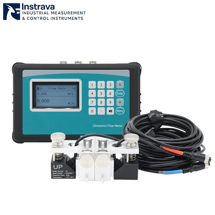
Flow Velocity Range : ±0.01 m/s ~ ±12 m/s | Pipe Size : 25mm ~ 1200mm (1″~48″)
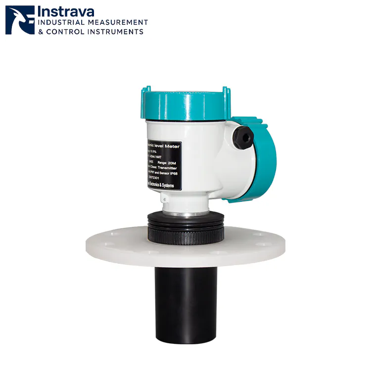
Measuring Range : 4m / 6m / 8m / 12m / 20m / 30m
Output Signal : 4–20mA (2-wire)
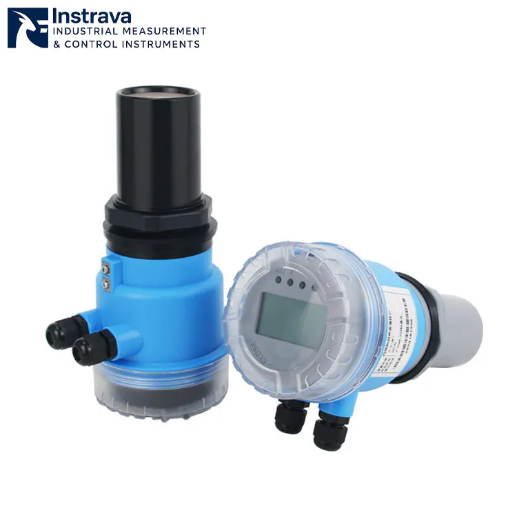
Wide measuring range (0–60m) | High accuracy (0.5%–1% FS)
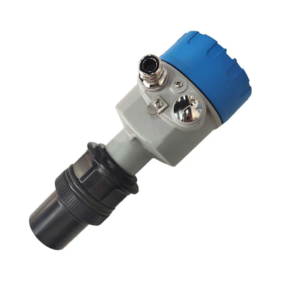
Measurement range: 0-60m
Working pressure: ATM
Download liquid level gauge product information EN document
The level gauge can be used for level measurement of various industrial media such as water, oil, chemical liquids, corrosive media, high-viscosity liquids and slurries.
Level gauges are critical components in modern industrial automation systems designed to monitor and control the height of liquids, solids, or interfaces within tanks, silos, vessels, and pipelines. These instruments provide real‑time level data that help prevent overflow, dry‑run conditions, and process interruptions — ensuring safety, efficiency, and compliance across various applications.
At Instrava, we offer a comprehensive portfolio of high‑performance level measuring instruments engineered for accuracy, durability, and seamless integration into industrial control systems.
What Is Level Gauge?
A level gauge (English: Level Gauge / Level Transmitter; Русский: Уровнемер; Español: Medidor de nivel; Français: Jauge de niveau) is an industrial instrument used to measure, monitor, and display the real-time height or volume of liquids, slurries, or granular solids inside a tank, vessel, or silo.
Acting as the “eyes” of industrial automation, it plays a critical role in process control, inventory management, and safety prevention across industries such as chemical processing, oil and gas, water treatment, and power generation.
Depending on the application, level gauges operate on various physical principles—ranging from simple visual indicators (like magnetic flaps) to advanced, non-contact electronic technologies like Radar, Ultrasonic, and Guided Wave Radar (GWR)—ensuring precise data transmission even under extreme conditions of high pressure, high temperature, or corrosive environments.
Common Types of Level Gauge
Industrial processes vary widely in media, conditions, and accuracy requirements. Below are the most widely used level gauges type:
1. Capacitive Level Gauge
Operates on the principle that the capacitance formed between the measuring probe and the vessel wall (or an auxiliary electrode) changes with the material level. Variations in the medium’s height alter the dielectric constant or the electrode coverage area, which is then converted into standard electrical signals.
✔ Zero Mechanical Wear: Compact structure with no moving parts, ensuring extremely low maintenance costs.
✔ High Pressure Resistance: Capable of operating stably under ultra-high pressure, high vacuum, or high-temperature environments.
✔ Versatile Applications: Highly suitable for measuring conductive/non-conductive liquids, highly corrosive media, and powders or granules.
2. Displacer Level Gauge
Based on Archimedes’ buoyancy principle. A displacer (internal cylinder) suspended from a spring or torque tube is immersed in the liquid. As the liquid level rises, the buoyant force on the displacer increases, reducing its apparent weight. The mechanical structure converts this weight change into a level signal.
✔ High-Precision Measurement: Exceptionally well-suited for measuring the interface between two liquids of different densities.
✔ Extreme Process Conditions: Exhibits excellent stability in large vessels under high temperatures, high pressures, and high vacuums.
✔ Turbulence Resistance: Compared to standard floats, the displacer provides superior suppression against turbulent surfaces or wave action.
3. Electrode Level Gauge (Conductivity Level Switch)
Utilizes the electrical conductivity of liquids to detect levels. When the liquid comes into contact with metal electrode rods of varying lengths, the electrical circuit closes, triggering a switch signal or controlling pump start/stop operations.
✔ Highly Cost-Effective: Simple configuration, making it one of the most economical solutions for level control.
✔ Rapid Response Time: Contact-type switching provides immediate, direct signal triggering.
✔ Ideal Applications: Exclusively designed for multi-point limit alarm and control of conductive liquids such as water, wastewater, acids, and alkalis.
4. Float Level Gauge
Operates on basic buoyancy, where a hollow float containing a magnet or connected to a mechanical link rides directly on the liquid surface. The vertical displacement of the float is converted into a mechanical indication or electrical output via connecting rods, wire ropes, or internal magnetic reed switches.
✔ Simple Structure: Proven, intuitive technology that is easy to install and maintain.
✔ High Cost-Performance: Ideal for continuous measurement in standard storage tanks, sumps, and open basins.
✔ Independent of Medium Properties: Measurement results are unaffected by changes in liquid density, electrical conductivity, or dielectric constants.
5. Glass Level Gauge
Based on the principle of communicating vessels. A robust transparent glass tube or flat plate assembly is connected directly to the side of the vessel. Due to pressure equalization, the liquid rises to an identical height within the glass chamber, allowing direct visual inspection by operators.
✔ Direct & Reliable: Provides 100% authentic local visual verification with zero power required.
✔ Severe Service Duty: Utilizes specialized explosion-proof and high-pressure reinforced glass, making it suitable for high-temperature, high-pressure boilers.
✔ Zero Electronic Failures: Completely immune to electromagnetic interference, signal loss, or electronic component aging.
6. Magnetic Level Gauge
Connected to the primary vessel via a bypass chamber containing an internal float with a built-in magnet. As the liquid level shifts, the float drives the external indicator—composed of red/white (or black/yellow) magnetic rollers—to flip 180°, delivering a high-contrast boundary display.
✔ High Local Visibility: Provides clear, long-distance visual indication of the level without needing an external power supply.
✔ Secure Isolation: Complete magnetic isolation between the measuring chamber and the indicator array ensures “zero leakage” of hazardous process media.
✔ Excellent Extensibility: Can be easily equipped with magnetostrictive sensors or magnetic switches to output synchronous 4-20mA remote transmission signals.
7. Magnetostrictive Level Gauge
The electronic housing emits a current pulse that travels down a waveguide wire, generating a circular magnetic field. When this field meets the magnetic field of the float riding on the liquid, a mechanical strain wave is generated and reflected back to the sensor head. The level is determined with extreme precision by calculating the Time-of-Flight (ToF).
✔ Ultra-High Precision: Accuracy typically reaches millimeter ($mm$) or micrometer ($\mu m$) levels, making it the preferred choice for custody transfer and commercial billing.
✔ Dual Interface Measurement: By utilizing floats with distinct densities, it can simultaneously and precisely measure the total level and the oil-water interface.
✔ Outstanding Stability: Entirely unaffected by variations in temperature, pressure, vapor, mist, or the dielectric constant of the medium.
8. Radar Level Gauge
A non-contact measurement technology. The antenna emits high-frequency microwave pulses (typically 26GHz or 80GHz) toward the material surface. The microwaves reflect off the medium, and the antenna receives the return echo, determining the distance by calculating the wave’s travel time or frequency differential.
✔ Robust Performance: Completely immune to vacuum, high pressure, extreme high temperatures (up to thousands of degrees), and heavy vapors.
✔ Zero-Maintenance Design: The non-contact probe eliminates issues related to corrosion, wear, coating, or scaling.
✔ High Focusing Capability: Modern high-frequency (e.g., 80GHz) radar features an extremely narrow beam angle, easily avoiding internal tank obstructions like agitators or ladders.
9. Ultrasonic Level Gauge
A non-contact measurement technology. The transducer (probe) mounted at the top emits high-frequency acoustic pulses. The sound waves strike the surface of the liquid or solid and reflect back. The probe receives the echo and calculates the level based on the round-trip travel time.
✔ Economic Non-Contact Solution: Offers the most competitive cost-performance ratio among non-contact measurement alternatives.
✔ Effortless Installation: Top-mounted, integrated design allows for plug-and-play deployment and highly intuitive commissioning.
✔ Ideal Applications: Extensively used in open-channel flow monitoring, municipal wastewater management, acid/alkali storage tanks, and atmospheric water applications.
How Level Gauge Work
The Universal Principle: The “Zero-Point” Distance Formula
While different level gauges use completely different physical mechanisms—ranging from mechanical floats to acoustic waves—almost all continuous electronic level gauges (like Radar, Ultrasonic, and Magnetostrictive) calculate the liquid level using a fundamental distance subtraction formula:
Tank Height ($H$): A fixed reference value configured into the gauge during installation (the distance from the sensor face to the bottom of the tank).
Measured Distance ($D$): The real-time distance from the sensor down to the liquid surface, which changes constantly.
How Each Type Works (The Physics Broken Down)
To understand how a specific level gauge works, we look at the exact physics it uses to find either that Distance ($D$) or the direct physical position of the fluid surface.
1. Non-Contact Radar & Ultrasonic (Time-of-Flight Principle)
Both technologies act like industrial “echolocators.”
The Action: A sensor mounted at the top of the tank fires a signal downward. Radar fires high-frequency microwave pulses (at the speed of light), while Ultrasonic fires acoustic sound waves (at the speed of sound).
The Reflection: The wave hits the liquid surface and bounces back up to the sensor.
The Calculation: The gauge’s internal microprocessor records the precise round-trip transit time ($t$). Since the speed of the wave ($v$) is known, it calculates the distance using:
2. Guided Wave Radar – GWR (Contact Microwave Guidance)
GWR functions similarly to standard radar, but with a physical guide.
The Action: Instead of broadcasting microwaves through the open air, GWR launches the pulse down a rigid metal rod or flexible cable probe immersed in the liquid.
The Reflection: When the pulse hits the boundary between the upper air/gas layer and the lower liquid, it encounters a sudden drop in the dielectric constant ($\varepsilon_r$). This electrical mismatch forces the microwave pulse to reflect straight back up the probe to the transmitter head, which measures the Time-of-Flight.
3. Magnetostrictive (Wiegand Effect & Magnetic Interaction)
This is one of the most precise methods for commercial and custody transfer applications.
The Action: The sensor head sends a high-speed electrical current pulse down a specialized ferromagnetic waveguide wire inside the probe tube. This current creates a temporary circular magnetic field around the wire.
The Intersection: A permanent magnetic float rides up and down the tube on top of the liquid. Where the circular magnetic field meets the float’s magnetic field, a physical distortional strain (a torsional wave) is instantly triggered in the wire (known as the Wiegand effect).
The Calculation: This mechanical wave travels back up the wire to the sensor head at a known speed of sound. The sensor calculates exactly where the float is located based on how long it took for the wave to arrive.
4. Magnetic Level Gauge (Bypass Magnetic Coupling)
A purely mechanical, highly visible method that requires zero electrical power.
The Action: A bypass chamber is mounted to the side of the tank. Because of the law of communicating vessels, the liquid inside the chamber always mirrors the level inside the main tank.
The Coupling: Inside the chamber, a sealed float containing strong permanent magnets rides the liquid surface. Outside the chamber, an airtight scale of interlocking, dual-colored magnetic rollers (usually red and white) is attached.
The Visual: As the float moves, its internal magnetic field reaches through the stainless steel chamber wall and physically flips the rollers 180°. The color boundary shifts instantly, creating a clear visual line.
5. Hydrostatic / Differential Pressure (Weight of the Liquid Column)
This method relies entirely on fluid mechanics.
The Action: A pressure sensor is placed at the very bottom of the tank. It detects the force exerted by the weight of the liquid directly above it.
The Calculation: The sensor calculates the height ($h$) using the standard hydrostatic equation:
(Where $P$ is pressure, $\rho$ is the known density of the fluid, and $g$ is gravity).
Note: For closed, pressurized tanks, a Differential Pressure (DP) transmitter is used. It measures both the bottom pressure and the top gas pressure, subtracting the top pressure so it only calculates the true weight of the liquid column.
6. Capacitive (The Liquid as an Electrical Component)
The Action: An insulated metal rod probe is inserted into the tank, acting as one plate of a giant electrical capacitor. The metal walls of the tank act as the second plate.
The Shift: Air has a dielectric constant ($\varepsilon_r$) of roughly 1, while process liquids have much higher values (e.g., water is $\approx 80$). As the liquid rises and displaces the air between the probe and the wall, the overall electrical capacitance increases proportionally. The transmitter detects this change in capacitance and scales it to a 0–100% level reading.
Industrial Applications of Level Gauge
Level gauges are indispensable across nearly every process industry. By providing precise data to distributed control systems (DCS), they prevent catastrophic overflows, protect expensive equipment, and ensure accurate inventory tracking.
The primary industrial sectors where level gauges are heavily deployed include:
1. Oil & Gas (Petrochemicals)
The oil and gas industry requires high-precision instruments capable of handling explosive vapors, toxic gases, and extreme pressures.
Applications: Oil-water interface measurement in separators, custody transfer tracking in large crude storage tanks, and monitoring liquefied natural gas (LNG) at cryogenic temperatures.
Preferred Gauges: Magnetostrictive Level Gauges (for high-accuracy dual interface tracking), Radar Level Gauges (80GHz non-contact for large tanks), and Displacer Level Gauges (for heavy-duty high-pressure separators).
2. Chemical Processing
Chemical plants handle aggressive, highly corrosive, and flammable fluids that can rapidly degrade standard mechanical instrumentation.
Applications: Bulk storage of highly concentrated acids (like sulfuric or hydrochloric acid), alkali mixing tanks, and high-temperature chemical reactors.
Preferred Gauges: Non-Contact Radar (with PTFE-coated horn antennas to resist corrosion) and Magnetic Level Gauges (utilizing specialized plastic or exotic metal linings like Hastelloy for zero-leakage local display).
3. Power Generation & Energy
Power plants rely heavily on steam cycles, requiring level measurement under severe high-temperature and high-pressure (HP) conditions.
Applications: Boiler steam drum level control, feedwater heater tracking, condenser hotwells, and oil level monitoring in massive power transformers.
Preferred Gauges: Glass Level Gauges (high-pressure reflex or transparent plates for direct steam boiler verification), Guided Wave Radar (GWR) (with dynamic vapor compensation to adjust for dense steam), and Differential Pressure (DP) Transmitters.
4. Water & Wastewater Treatment
Water treatment facilities require rugged, cost-effective, and low-maintenance solutions capable of handling open-air environments and dirty, debris-filled fluids.
Applications: Sewage wet wells, clarifier tanks, chemical dosing skids (alum, chlorine), and open-channel flow monitoring (weirs/flumes).
Preferred Gauges: Ultrasonic Level Gauges (the primary economic choice for open-air basins), Float Level Gauges/Switches (for pump control and overflow prevention), and Electrode Level Gauges (for simple multi-point limit alarms in clean water tanks).
5. Food, Beverage & Pharmaceuticals
Sanitation is paramount in these sectors. Instruments must comply with strict hygienic standards (like 3A or EHEDG) to prevent bacterial growth and survive Clean-In-Place (CIP) or Sterilize-In-Place (SIP) washdown cycles.
Applications: Dairy storage silos, fermentation vessels, beer brewing tanks, and pure water purification loops.
Preferred Gauges: Capacitive Level Gauges (hygienic flush-mount designs), Non-Contact Radar (with stainless steel housings and sanitary tri-clamp fittings), and Hydrostatic Pressure Sensors (hygienic diaphragm type).
How to Choose the Right Level gauge
Selecting the right level gauge is about matching your specific process conditions with the physical limits of the measurement technology. There is no single “perfect” level gauge—only the right gauge for your specific application.
To make the right choice, engineers follow a systematic 4-step selection process.
The 4-Step Selection Process
Step 1: Characterize the Medium
The physical and chemical properties of what you are measuring eliminate half of your options immediately.
State: Is it a clean liquid, slurry, paste, or bulk solid (powders/granules)? Ultrasonic struggles with heavy dust solids; Radar or Capacitive handles them better.
Corrosivity: Will it eat through stainless steel? Aggressive chemicals require non-contact radar or magnetic gauges with PTFE/PP linings.
Electrical Properties: For Radar and GWR, check the Dielectric Constant ($\varepsilon_r$). Low $\varepsilon_r$ fluids (like oils or solvents) reflect weak radar signals. For Electrode gauges, the liquid must be conductive.
Step 2: Define Process Conditions
Exceeding a gauge’s operating limits leads to immediate instrument failure or unsafe leakage.
Temperature & Pressure: High-pressure boilers or cryogenic tanks require heavy-duty mechanical options (Glass/Magnetic gauges) or high-frequency Non-Contact Radar.
Vapor & Foam: Heavy steam or surface foam dampens acoustic waves (Ultrasonic) and open-air microwaves (Radar). Guided Wave Radar (GWR) or Hydrostatic DP transmitters are much more stable here.
Step 3: Assess Tank Geometry & Installation
Where and how the gauge mounts dictates the mechanical form factor.
Internal Obstructions: Does the tank have agitator blades, heating coils, or structural baffles? Standard radar beams might bounce off them. Use a narrow 80GHz radar or a GWR probe inside a bypass chamber.
Mounting Connections: Check the top or side nozzle size and rating (e.g., Flanged or Threaded Tri-clamp). Side connections require Magnetic or Glass gauges; top connections favor Radar, Ultrasonic, or Floats.
Step 4: Determine Function & Budget
Indication vs. Control: Do you just need a local operator to see the level (Magnetic/Glass), or do you need a continuous signal (4-20mA, HART, Modbus) sent to a DCS/PLC?
Accuracy Requirements: Is this for rough inventory monitoring ($\pm 10\text{ mm}$ is fine) or high-value custody transfer commercial billing where millimeter ($\pm 1\text{ mm}$) accuracy is mandatory? For custody transfer, choose Magnetostrictive or high-precision Radar.
Technology Selection Matrix
Use this quick-reference table to cross-match your dominant process challenge with the ideal technology:
| If your process has… | Best Technology Choice | Why it works | What to Avoid |
| Heavy Surface Foam | Guided Wave Radar (GWR) / Hydrostatic | Traverses through foam to find the true liquid layer | Non-Contact Radar / Ultrasonic (signals get absorbed) |
| Aggressive Acids ($HCl, H_2SO_4$) | Non-Contact Radar (PTFE) / Magnetic (Plastic Lined) | No metal contact with the corrosive fluid | Standard metallic floats or bare probes |
| Internal Agitators / Obstacles | 80GHz Radar / Magnetic Bypass | Narrow beam avoids obstacles; bypass isolates the measurement | Wide-beam Radar or loose float switches |
| Vapor / Heavy Steam Layers | Hydrostatic DP / GWR with Vapor Comp | Pressure and guided probes are unaffected by ambient gas | Ultrasonic (speed of sound changes with gas density) |
| High Accuracy Custody Transfer | Magnetostrictive / 80GHz Radar | Provides millimeter-level repeatability | Hydrostatic DP (affected by temperature/density shifts) |
| Zero Power / Remote Fields | Magnetic Level Gauge / Glass Gauge | Relies entirely on mechanical buoyancy and optics | All electronic transmitters |
Pro Tip: When dealing with sticky, coating-prone fluids (like wastewater sludge or resins), always lean toward non-contact technologies (Ultrasonic or Radar). Contact probes will inevitably suffer from product buildup, causing the sensor to output false high-level readings.
Level Gauge Knowledge Hub
This page provides a structured, engineering-focused overview of industrial level measurement. It is designed to support selection, application, and system design decisions rather than basic definitions. The content reflects real process conditions and long-term operational considerations.
1. Role of Level Measurement in Industrial Systems
Level measurement is a core component of process safety, control, and inventory management. In industrial environments, level information is rarely used in isolation. It supports interlocks, alarms, batch control, and material balance. The value of a level measurement device lies not only in accuracy, but in its stability, availability, and compatibility with the overall system.
Key objectives of level measurement systems include:
Preventing overfill or dry-run conditions
Maintaining process continuity and balance
Supporting safety-related functions
Providing reliable data for automation and optimization
2. Level Gauge, Level Sensor, and Level Transmitter – System Roles
Different level measurement devices serve different roles within a system:
Level gauges provide local visual indication for operators and maintenance personnel.
Level sensors convert level changes into electrical signals for control or alarm purposes.
Level transmitters deliver standardized outputs for integration with PLC, DCS, or SCADA systems.
In many applications, these devices are used together to provide redundancy, cross-verification, and operational flexibility. Selecting the right combination is often more important than choosing a single device type.
3. Key Selection Factors for Level Measurement Devices
Effective selection starts from process conditions rather than product type. Critical factors include:
Process medium properties such as density, viscosity, corrosiveness, foaming, or solids content
Operating pressure and temperature ranges
Vessel geometry and installation constraints
Required response time and signal stability
Maintenance access and lifecycle cost considerations
A level sensor that performs well in laboratory conditions may behave very differently in a real industrial environment. Selection should prioritize reliability under actual operating conditions.
4. Application-Oriented Measurement Challenges
4.1 High-Pressure and High-Temperature Vessels
In pressurized or high-temperature applications, mechanical integrity and sealing reliability become critical. Level gauges and level sensors must maintain performance without material degradation or signal drift over time.
4.2 Media with Foaming, Coating, or Solids
Foaming liquids, sticky media, or suspended solids can interfere with level measurement. Certain measurement principles tolerate these conditions better than others. Proper matching of technology and wetted materials reduces false readings and maintenance frequency.
4.3 Dynamic Process Conditions
Rapid filling, emptying, or agitation introduces turbulence that can distort level readings. Installation position and damping characteristics of the level sensor play a key role in achieving stable measurement.
5. Installation and System Integration Considerations
Installation quality directly affects level measurement performance. Important aspects include:
Nozzle location relative to inlets, outlets, and agitators
Vertical alignment and mounting rigidity
Electrical grounding and signal shielding
Integration with control systems and alarm logic
A well-designed installation often improves measurement reliability more than incremental improvements in sensor accuracy.
6. Reliability, Redundancy, and Safety Strategy
In safety-related applications, level measurement is rarely dependent on a single device. Common strategies include:
Combining local level gauges with independent level sensors
Using separate devices for control and high-level alarms
Implementing fault detection and signal validation in the control system
These approaches reduce the risk of undetected failure and support safe operation under abnormal conditions.
7. Maintenance, Calibration, and Lifecycle Cost
Lifecycle cost is influenced by more than purchase price. Key contributors include:
Calibration frequency and accessibility
Cleaning or inspection requirements
Spare parts availability
Downtime during maintenance activities
Selecting level measurement devices with low maintenance demands can significantly reduce total cost of ownership over the system lifecycle.
8. Industry-Specific Level Measurement Practices
Level measurement practices vary by industry:
Process industries prioritize robustness and long-term stability
Water and wastewater applications emphasize corrosion resistance and ease of maintenance
Oil and gas applications often require compliance with hazardous area standards
Understanding industry-specific expectations helps align measurement strategy with operational reality.
9. Common System-Level Mistakes in Level Measurement
Frequent issues encountered in level measurement projects include:
Selecting devices based solely on accuracy specifications
Ignoring installation constraints during design
Underestimating the impact of process variation
Relying on a single measurement point for safety-critical functions
Avoiding these mistakes requires a system-level perspective rather than a product-centric approach.
10. Building a Robust Level Measurement Strategy
A robust level measurement strategy considers device selection, installation, integration, and maintenance as a unified system. By focusing on long-term performance and operational context, level gauges and level sensors can deliver consistent value throughout the life of the plant.
This knowledge structure is intended to support informed decision-making and continuous improvement in industrial level measurement systems.
Level Gauge-FAQ
How should a level gauge be selected for long-term industrial operation?
Level gauge selection should be based on operating conditions such as pressure, temperature, medium properties, and installation constraints. For continuous operation, stability and resistance to process variation are often more important than laboratory accuracy. In many industrial systems, the level gauge also functions as a level sensor for control or alarm purposes, so signal reliability over time is a critical factor.
What factors most commonly affect level measurement accuracy in real applications?
In real process environments, accuracy is influenced by medium density changes, temperature fluctuation, mechanical vibration, and buildup on wetted parts. Unlike ideal test conditions, industrial level gauges must tolerate these factors while maintaining repeatable output. Selecting a level sensor designed for the actual process conditions significantly reduces long-term deviation.
How does installation position influence level gauge performance?
Installation position directly affects measurement reliability. Nozzle orientation, vessel geometry, and proximity to inlets or agitators can introduce turbulence or false readings. Proper positioning ensures that the level gauge or level sensor reflects true liquid level rather than localized disturbances within the vessel.
When should a local level gauge be combined with a level transmitter or level sensor?
Local level gauges provide visual confirmation and are often used for routine inspection, while level sensors or transmitters enable remote monitoring and control. In many applications, combining both improves operational safety by offering redundancy and cross-verification between visual indication and electronic signal output.
How do process media properties impact level gauge and level sensor selection?
Media properties such as viscosity, corrosiveness, foaming tendency, and presence of solids play a major role in selection. Certain level gauges perform well with clean liquids but may struggle with sticky or abrasive media. Matching the level sensor design and wetted materials to the medium helps prevent measurement drift and mechanical failure.
What are common challenges when using level gauges in high-pressure or high-temperature vessels?
High-pressure and high-temperature conditions place additional stress on seals, materials, and measurement components. Under these conditions, a level gauge must maintain mechanical integrity while the level sensor remains stable and responsive. Selecting designs rated for the full operating envelope is essential for safe and reliable measurement.
How is reliability evaluated for level gauges used in safety-related applications?
Reliability is evaluated based on long-term stability, resistance to process upset, and consistency of output under varying conditions. In safety-related applications, level gauges are often used alongside independent level sensors to provide layered protection and reduce the risk of undetected level deviation.
What maintenance considerations affect the lifecycle cost of a level gauge?
Maintenance frequency, accessibility, and recalibration requirements directly impact lifecycle cost. A level gauge that requires frequent cleaning or adjustment may appear cost-effective initially but increases downtime and maintenance effort. Choosing a level sensor with low maintenance requirements improves overall system efficiency.
Can one level gauge design cover multiple tank or vessel configurations?
While some level gauges offer flexible mounting options, optimal performance is typically achieved when the design is matched to the vessel type. Vertical tanks, horizontal vessels, and pressurized containers each impose different measurement challenges, making application-specific selection an important consideration.
How do level gauges and level sensors support process control and optimization?
Beyond indication, level gauges and level sensors provide critical input for inventory management, process control, and alarm systems. Stable and accurate level data helps operators maintain process balance, prevent overfill or dry-run conditions, and improve overall operational efficiency.
Why Trust Instrava?
We select manufacturers from a neutral, impartial standpoint, always with your best interests in mind.
Our very existence depends on helping you source the products that are the perfect fit for your needs.
Based in China, we are able to conduct on-site inspections of production environments and product quality firsthand.
We help you avoid intermediaries posing as factories.
We facilitate smoother after-sales support, eliminating time zone issues and the delays often associated with dealing directly with factories.
Our multilingual team ensures effective communication.
For a trading startup, every interaction with a client is a precious opportunity—a sign that you are willing to place your trust in us and give us the chance to prove ourselves.
In the digital age, while information is easily accessible, misconceptions often cloud the trust between people.
Instrava relies entirely on trust; it is our core philosophy and the foundation of our existence in society. It is the fundamental basis for our long-term growth and our commitment to serving the community.
Please place your trust in us.