
Accueil » Technologie » Digital Elevation of Industrial Direct-Reading Instruments: Technical Evolution, Core Mechanisms, and Industry 4.0 Outlook of Glass Plate Level Gauges
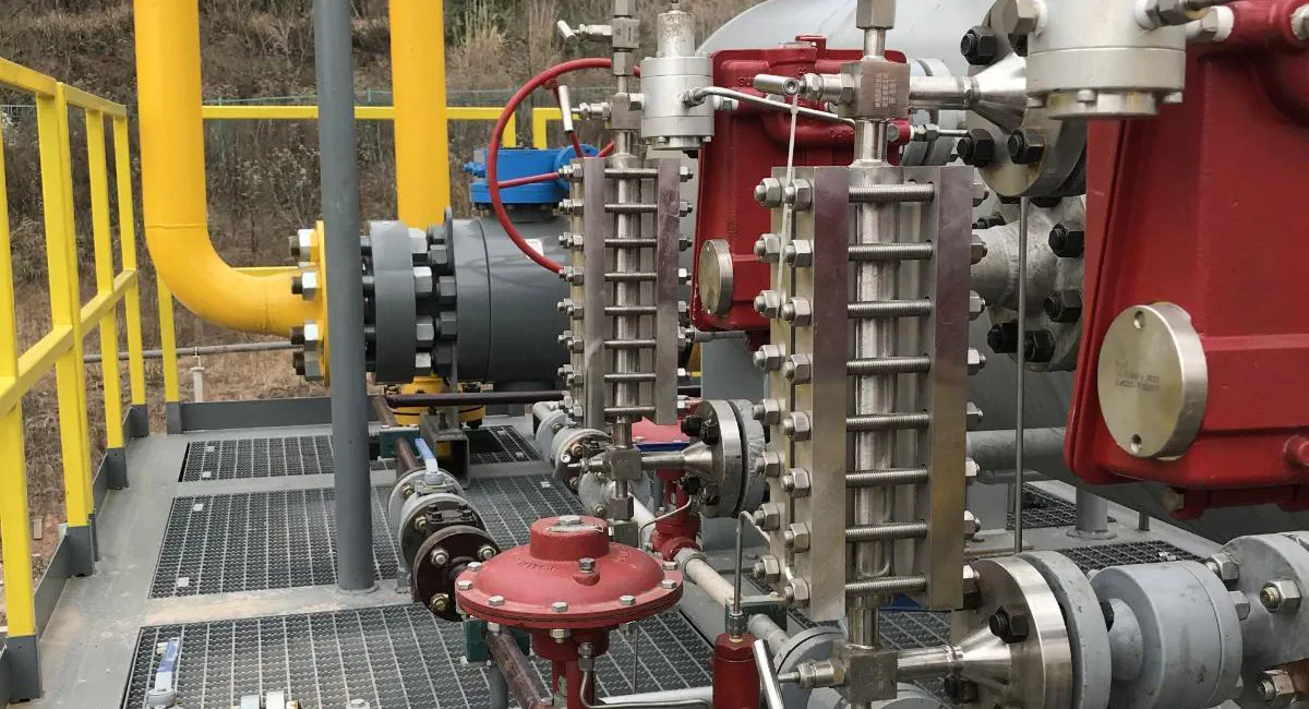
Digital Elevation of Industrial Direct-Reading Instruments: Technical Evolution, Core Mechanisms, and Industry 4.0 Outlook of Glass Plate Level Gauges
Introduction
In today’s rapidly changing landscape of process industries and automation technologies, electronic level meters such as radar, ultrasonic, and guided wave radar have occupied the lion’s share of the market. However, under extreme working conditions involving high temperatures, high pressures, extreme flammability, explosiveness, or strong corrosion, a classical instrument still firmly holds the “last line of defense” for plant safety—the Glass Plate Level Gauge.
As a mechanical instrument that relies entirely on physical mechanisms, requires no electrical power, and offers 100% direct reading, the technical evolution of the glass plate level gauge is not only a microcosm of the application of industrial hydrostatics but also a typical exemplar for brownfield retrofitting and edge AI upgrading in modern smart factories (Industry 4.0). This paper systematically analyzes the technological essence of this traditional instrument from the perspectives of its operating principles, evolution, core technologies, solutions to industry pain points, advanced theoretical enhancements, and future trends in the Industry 4.0 era.
1. Operating Principles, Evolutionary History, and Underlying Logic
1.1 Core Operating Principle
The underlying physical logic of the glass plate level gauge is remarkably simple yet infallible: the Principle of Communicating Vessels. According to hydrostatics, when a liquid remains static in freely connected vessels and the pressure above the liquid level in each vessel is equal, the liquid levels in all vessels must maintain the exact same horizontal plane. By introducing the process medium into the cavity of the glass window, the real liquid level inside the vessel is duplicated at an identical height, allowing for direct observation by human eyes or optical equipment.
1.2 Historical Evolution and Driving Forces
The glass level gauge has undergone three major technological iterations, each driven by escalating industrial safety standards and the demands of extreme operating conditions:
1.Tubular Glass Level Gauge (Early Era: High Risk, Low Pressure)
2.Flat Glass Level Gauge (Middle Era: Armored Explosion-Proof, Optical Enhancement)
3.High-Pressure Mica/Bi-Color Glass Level Gauge (Modern Era: Supercritical, Chemical Protection)
First Generation: Tubular Glass Level Gauge
Origin: The earliest form consisted of a transparent, cylindrical, thin-walled glass tube connected directly to the side of a vessel via valves.
Limites techniques: Extremely poor safety. Cylindrical thin-walled glass tubes generally have a pressure rating below $1.6\text{ MPa}$ and are highly brittle. Any severe pressure fluctuations (such as water hammer effects) or external impacts can shatter the glass tube, causing instantaneous spraying of high-temperature, high-pressure, or toxic media, leading to severe safety accidents.
Second Generation: Flat Glass Level Gauge
Origin: To overcome pressure containment and safety issues, engineers replaced the “cylindrical tube” with a “thick flat plate” and enclosed it within a heavy metallic housing (gauge body).
Evolutionary Logic: The combination of thick tempered borosilicate glass and metallic armor exponentially increased pressure and impact resistance. Furthermore, to address the challenge of indistinguishable liquid levels when measuring pure, transparent liquids through thick glass, two variants emerged: the Reflex type (utilizing prism refraction principles where the liquid phase appears black and the gas phase appears silvery-white) and the Transparent type (used for observing interfaces or dirty media).
Third Generation: High-Pressure Mica/Bi-Color Glass Level Gauge
Origin: As the industry entered the ultra-high-pressure steam era (such as supercritical boilers in modern thermal power plants), high-temperature, high-purity boiler water rapidly dissolved and eroded the glass, while the density difference between the gas and liquid phases narrowed drastically.
Evolutionary Logic: Natural mica sheets were introduced as a protective lining for the glass to isolate it from the medium. Simultaneously, red and green filters were integrated (red indicating gas, green indicating liquid), completely solving the visual challenge of distinguishing the gas-liquid interface under high pressure.
2. Detailed Explanation of Core Technologies
A modern industrial-grade glass plate level gauge is far more than a simple assembly of glass and steel plates. Its long-term stable operation under high-pressure and extreme temperature-differential conditions relies on three core pillars spanning materials science, mechanical structures, and optical applications:
Core Technology 1: High-Strength Borosilicate Glass Manufacturing and Tempering Processes
Industrial glass plates must undergo extremely rigorous thermal tempering processes to form a uniform and deep compressive stress layer on their surfaces. High-quality borosilicate glass or aluminosilicate glass possesses exceptional thermal shock resistance (capable of withstanding abrupt temperature drops or rises of over $200^\circ\text{C}$) and immense tensile and compressive strength, providing the material foundation to withstand hundreds of kilograms of industrial pressure.
Core Technology 2: Uniform Stress Distribution and Sealing-Clamping Technology
Under high pressures and frequent thermal cycling, the contact interface between the glass and the metallic gauge body is highly susceptible to stress concentration, leading to localized glass fracturing. The core technology lies in the precision mechanical machining of the metal gauge body (maintaining flatness within the micron level), the precise formulation of high-performance flexible graphite/PTFE gaskets, and a staggered bolt-tightening structure with strictly controlled torque. Its primary objective is to ensure that the glass experiences completely uniform stress distribution during long-term thermal expansion and contraction, achieving “absolute zero leakage.”
Core Technology 3: Reflex Prism Optical Technology
Reflex level gauges utilize the classical Theory of Total Internal Reflection. The inner side of the glass plate is machined with fine, continuous longitudinal $90^\circ$ prism grooves:
Gas Phase: When light enters, due to the low refractive index of the gas phase, total internal reflection occurs at the prism interface. The light is reflected fully back into the observer’s eyes, appearing as a bright, crystalline silvery-white.
Liquid Phase: The refractive index of the liquid is close to that of the glass, breaking the conditions for total internal reflection. The light penetrates directly through the interface and is absorbed by the black coating on the back of the metal gauge body, appearing as a deep black. This stark black-and-white contrast drastically reduces the probability of human misreading.
Core Technology 4: Automatic Safety Shut-Off Technology (Check Valve)
Précision stainless steel balls are integrated inside both the upper and lower connecting valves. During normal operation, the balls remain static at the bottom of the valve cavity due to gravity. Should the glass plate accidentally fracture under an irresistible force, the high-pressure medium inside will burst outward instantaneously. The immense flow velocity differential generates a pressure drop across the valve seat, instantly “sucking” and pushing the steel ball onto the valve seat. This automatically cuts off the medium leakage channel, forging the ultimate safety barrier to protect field personnel.
3. Industrial Applications and Process Pain Points Addressed
Despite the widespread adoption of electronic instrumentation, glass plate level gauges remain irreplaceable “golden baselines” in specific industries due to their attributes of being “independent of algorithms, completely unpowered, and featuring zero control-loop failure rates.”
3.1 Power and Thermal Industries (Thermal Power Plants, Captive Boiler Rooms)
Specific Process Pain Points: Boiler steam drums operate under ultra-high pressures (often $> 22 \text{ MPa}$) and high temperatures ($> 300^\circ\text{C}$). The high-purity boiler water is highly aggressive in dissolving glass, and the density difference between the gas and liquid phases shrinks dramatically. At these thresholds, electronic instruments like guided wave radars are prone to interference from dielectric constant fluctuations in ultra-high-pressure saturated steam, while magnetic level indicators suffer from high-temperature demagnetization or float jamming. Should a steam drum become overfilled (leading to carryover that damages steam turbine blades) or run dry (causing boiler explosions), the consequences are catastrophic.
Solution: High-pressure bi-color flat glass level gauges (with mica protection) serve as the highest-safety-level direct-reading physical instrument mandated by regulatory standards. Unaffected by fluctuations in dielectric constants, density changes, or electromagnetic interference, their distinct red-and-green display allows operators to confirm the true water level with 100% certainty, either remotely or on-site.
3.2 Petroleum and Petrochemical Industries
Specific Process Pain Points: Alkylation units, hydrocracking columns, and liquefied petroleum gas (LPG) storage tanks contain media characterized by high pressures, extreme flammability, explosiveness, and severe toxicity, demanding ultra-high explosion-proof ratings. In extreme disaster scenarios—such as plant-wide power outages or a total failure of the Distributed Control System (DCS) due to lightning strikes—all electronic instruments collectively go “blind.”
Solution: Armored plate level gauges contain no electrical components and are inherently intrinsically safe. In such crises, field operators can still accurately read the true liquid levels in columns and tanks via the glass plates, thereby guiding safe depressurization and emergency dispatching to prevent secondary disasters.
3.3 Pharmaceutical and Fine Chemical Industries
Specific Process Pain Points: Reactor vessels are frequently filled with strong acids (e.g., hydrochloric acid, hydrofluoric acid), strong alkalis, or aggressive organic solvents (e.g., chloroform, toluene), which easily corrode metallic housings or electronic electrodes. Furthermore, certain process media exhibit a high tendency to crystallize at ambient temperatures or possess extreme viscosity, leading to scaling and subsequent failure of conventional instruments.
Solution: The utilization of PTFE (Polytetrafluoroethylene)-lined or special corrosion-resistant film-lined transparent flat glass level gauges, augmented with steam heating jackets, resolves these issues. Because glass and PTFE exhibit exceptional chemical inertness and the heating jacket prevents medium crystallization, this setup perfectly solves the industry problem of instrument dissolution and perforation caused by highly corrosive media.
4. Advanced Theoretical Enhancements and R&D Outlook
To elevate the performance of traditional instruments and overcome their inability to output signals, upgrades can be achieved by introducing materials science surface-modification nanotechnology, total internal reflection photoelectric detection theory, et digital twin architectures:
4.1 Maintenance-Free Anti-Adhesion High-Pressure Level Gauge
Theoretical Framework: Superhydrophobic/Superoleophobic Surfaces theory et le Wenzel / Cassie-Baxter wetting models. By studying the influence of micro-nano structures under varying roughness on fluid contact angles (derived from research on sustainable superhydrophobic coatings in Progress in Organic Coatings / ACS Applied Materials & Interfaces), it is demonstrated that micro-nano structures can significantly reduce the nucleation probability of solutes on solid surfaces.
R&D and Pain Point Resolution: A highly stable, nano-modified silica ($\text{SiO}_2$) fluorosilane coating is sintered onto the borosilicate glass surface via the sol-gel method. This product renders the liquid completely non-wetting, thoroughly resolving the fine chemical industry’s pain point where media scaling and fouling render the glass window dirty and unreadable. This achieves a maintenance-free lifecycle on-site without manual cleaning.
4.2 Non-Contact Photoelectric Digital Twin Direct-Reading Level Gauge
Theoretical Framework: Total Internal Reflection Photoelectric Detection theory et Fresnel’s equations for light transmission and refraction. This relies on the sharp contrast in light intensity when light undergoes total internal reflection at the “glass-air” interface (extremely high intensity) versus transmission at the “glass-liquid” interface (extremely low intensity) (mechanisms frequently published in authoritative journals such as IEEE Sensors Journal).
R&D and Pain Point Resolution: Development of a non-contact linear image sensor scanning strip that clips onto the exterior of the glass plate. By capturing light intensity gradients across the glass window in real-time, the system performs digital encoding externally and outputs standard industrial signals (e.g., MQTT, Ethernet-APL). This preserves the absolute physical reliability of the glass direct reading while perfectly resolving the traditional mechanical instrument’s pain point of being “unable to transmit data remotely and operating as an information island,” enabling seamless integration into digital twin systems.
5. Summary of Industry Problems, Product Types, and Parameters
To address the extreme working conditions of various industries, precise selection of glass plate level gauges must be enforced. The specific parameters and selection logic are summarized in the table below:
| Industry Domain | Specific Process Pain Points & Challenges | Recommended Product Type Selection | Core Technical Parameters | Critical Special Configurations |
| Power & Thermal | Ultra-high pressure, ultra-high temperature, glass dissolution by boiler water, blurred gas-liquid boundaries | High-Pressure Multi-Window Bi-Color Quartz/Mica Level Gauge | • Operating Pressure: $\le 32 \text{ MPa}$ • Operating Temperature: $\le 560^\circ\text{C}$ • Body Material: Premium Carbon Steel / Alloy Steel | High-purity natural mica protective lining, red/green bi-color LED backlight |
| Pétrochimie | Flammable and explosive media, high pressures, lack of field power, strict explosion-proof mandates | Armored Reflex Plate Level Gauge | • Operating Pressure: $\le 10 \text{ MPa}$ • Operating Temperature: $-40^\circ\text{C} \sim 400^\circ\text{C}$ • Body Material: 304 / 316L Stainless Steel | High-pressure check valves with automatic ball-lock, explosion-proof area illuminators |
| Corrosive Chemicals | Strong acids (e.g., HCl, mixed acids) and alkalis rapidly corroding metals and standard glass | Transparent Lined Corrosion-Resistant Level Gauge | • Operating Pressure: $\le 2.5 \text{ MPa}$ • Operating Temperature: $\le 150^\circ\text{C}$ • Body Lining: PTFE / PFA | Special corrosion-resistant thin film (e.g., PVDF or high-adhesion mica) applied to the inner glass face |
| Cryogenic Liquefied Gas | LPG/LNG media vaporize easily; frost accumulation severely obstructs visibility through the glass | Transparent Anti-Frost / Jacketed Insulation Level Gauge | • Operating Pressure: $\le 4.0 \text{ MPa}$ • Operating Temperature: $\ge -196^\circ\text{C}$ • Body Material: 316L Cryogenic Stainless Steel | Vacuum-jacketed insulation or ultra-thick polymethyl methacrylate (anti-frost acrylic extension block) |
6. Development Trends and Empirical Foundations in the Industry 4.0 and AI Era
Linking a purely mechanical, direct-reading instrument to the era of Industry 4.0 and AI is by no means a flight of fancy; rather, it represents an inevitable “Retrofitting” pathway in the digital transformation of the process industry. Below are accurate trend assessments for the networkization and intelligentization of this product, backed by underlying industrial logic:
Trend 1: Seamless Integration of Edge AI Vision
Manifestation: Future glass level gauges will be equipped with or retrofitted with low-power industrial miniature Edge AI camera all-in-one units. The AI runs lightweight Convolutional Neural Networks (CNNs) directly at the edge to recognize the red-green bi-color or black-white boundary lines in real-time, converting visual images into precise $0 \sim 100\%$ digital level signals directly on-site. Simultaneously, AI algorithms utilize contrast enhancement and image restoration to adaptively identify windows that have become partially fouled or blurred.
Industrial Rationale: With the drastic price drop of embedded NPU chips and the proliferation of explosion-proof camera technologies, this retrofitting approach is thoroughly viable both technically and economically. Modern mega-scale petrochemical and thermal plants are implementing unmanned operations/dark factories, yet Hazard and Operability (HAZOP) safety studies strictly mandate the retention of a physical line of defense for extreme conditions; hence, glass plate level gauges absolutely cannot be eliminated. To enable these indispensable mechanical gauges to report data automatically, external Edge AI vision presents the most cost-effective and reliable intelligent upgrade strategy. Currently, major state-owned oil enterprises have already deployed numerous brownfield retrofitting cases of this nature within their smart factory construction frameworks.
Trend 2: Predictive Maintenance (PHM) Based on Anomaly Detection
Manifestation: By attaching MEMS micro-vibration sensors, temperature sensors, and piezoelectric thin-film stress sensors to the metallic gauge body or clamping bolts, an AI system can monitor the stress degradation of the level gauge under long-term high-pressure thermal shocks in real-time.
Industrial Rationale: The primary safety hazard of traditional glass level gauges stems from “sudden catastrophic blowouts” caused by high-pressure steam erosion and thinning, which forces emergency depressurization and plant shutdowns. Under the Asset Health Management framework of Industry 4.0, AI anomaly detection algorithms, by learning the waveforms of normal thermal expansion and contraction, can issue replacement alerts weeks before a glass blowout occurs when micron-level deformations manifest due to corrosion-induced thinning or bolt loosening. This shifts operations from reactive firefighting to proactive prevention.
Trend 3: “Single Cable to the Edge” via Ethernet-APL and Digital Twins
Manifestation: Upgraded intelligent glass level gauges will completely abandon traditional 4-20mA analog signals. Through the Advanced Physical Layer for Industrial Ethernet (Ethernet-APL), they will achieve high-bandwidth, long-distance, intrinsically safe field connectivity.
Industrial Rationale: The Ethernet-APL standard has bridged the “last mile” of communication in hazardous industrial areas (Zone 0/1). Leveraging this channel, intelligent glass level gauges can upload not only precise level data and equipment health diagnostic results but can also push real-time high-definition video streams directly to remote central control rooms or 3D digital twin dashboards, completely eliminating automation blind spots within the physical plant.
Conclusion
The evolution of the glass plate level gauge in the era of AI and Industry 4.0 does not mean forcibly altering its classical hydrostatic core. Instead, it involves leveraging peripheral AI vision, intelligent sensing, and advanced industrial networks to draw this stubborn, traditional, and irreplaceable physical blind spot into the lifecycle management network of the digital factory. This collision of “classical physics” and “cutting-edge intelligence” encapsulates the very essence of modern process industry transformation.
The glass on a high-pressure steam boiler's glass level gauge is constantly fogging up; how can this be resolved?
Root Cause AnalysisIn high-pressure steam boilers (such as steam drums), what is commonly referred to as “fogging” is typically not standard water vapor condensation on the surface. Instead, it is the result of chemical dissolution and micro-scouring of the glass component (Silicon Dioxide, $\text{SiO}_2$) by high-temperature, high-pH boiler water. This erosion roughens the flat glass surface at a microscopic level, creating diffuse light reflection that appears to the human eye or a camera as “persistent fogging or blurring.”
In-Depth Solutions
1.Install a High-Purity Natural Mica Shield Lining:
This is the most mature and widely adopted physical isolation solution in the industry. Placing a natural mica sheet with a thickness of approximately $0.2 \text{ to } 0.3 \text{ mm}$ between the tempered glass plate and the process medium (saturated steam and boiler water) provides excellent resistance against high temperatures and high-pH alkaline water corrosion. It completely blocks the scouring and dissolution of the glass.
2.Upgrade to Aluminosilicate Glass:
For ultra-high-pressure applications where conventional borosilicate glass exhibits poor dissolution resistance, upgrading to aluminosilicate glass is recommended. Its chemical stability and resistance to hot alkaline corrosion are significantly superior to standard industrial glass.
3.Introduce Nano-Modified Anti-Condensation Coatings (Cutting-Edge):
In vapor-phase zones experiencing pure condensation fogging due to temperature differentials, a superhydrophobic nano-$\text{SiO}_2$ coating can be sintered onto the exterior of the glass (or the non-scoured surface without mica protection). When condensation droplets form, their extreme contact angle forces them to slide off rapidly, preventing the formation of a continuous water film that obstructs visibility.
What factors should be considered when using a glass level gauge to perform precise measurements?
Although glass plate level gauges are “direct-reading” instruments, several hydrostatic and thermodynamic physical errors must be accounted for during precision custody transfer or under fluctuating operating conditions:
Density Gradient Errors Induced by Ambient Temperature Differentials:
The medium inside the main vessel (e.g., columns, tanks) is typically at a high temperature, whereas the external glass level gauge is exposed to ambient air (if uninsulated). Consequently, the temperature of the medium inside the level gauge is noticeably lower than that inside the vessel.
Consequence: The density of the cooler liquid in the gauge ($\rho_{\text{gauge}}$) becomes greater than the density of the hotter liquid inside the tank ($\rho_{\text{tank}}$). Based on the hydrostatic equilibrium formula for communicating vessels:
$$\rho_{\text{tank}} \cdot g \cdot H_{\text{tank}} = \rho_{\text{gauge}} \cdot g \cdot H_{\text{gauge}}$$
Because $\rho_{\text{gauge}} > \rho_{\text{tank}}$, the liquid level displayed by the gauge ($H_{\text{gauge}}$) will be significantly lower than the actual liquid level inside the vessel ($H_{\text{tank}}$). In tall column measurements, this physical error can amount to several centimeters.
Correction: A heating/insulation jacket must be installed around the level gauge body, or real-time density compensation calculations based on the temperature differential across both ends must be integrated into the control system.
Vapor-Phase Condensation and Reflow Fluctuations:
When high-boiling-point materials condense in the upper vapor-phase piping and flow down along the walls of the level gauge, they create localized turbulence and false high readings inside the liquid chamber. To mitigate this, ensure the upper vapor-phase tie-in piping has an adequate slope to allow the condensate to drain back into the primary vessel.
Capillary Effects:
In older tubular glass gauges or plate-type gauges with exceptionally narrow channels, a liquid chamber internal diameter below $10 \text{ mm}$ allows the liquid’s surface tension against the glass to cause a concave or convex meniscus.
Countermeasure: Modern flat glass level gauges feature chamber widths well exceeding the critical capillary dimension. However, when reading the black boundary line of a reflex gauge, the operator’s line of sight must be kept perfectly level with the bottom of the liquid meniscus.
To enhance the instrument's dynamic performance, is it permissible to omit the valves installed on the glass level gauge's connecting pipes?
Conclusion
Absolutely not. Omitting these valves is a severe violation of engineering safety standards.
In-Depth Rationale
Some field technicians believe that the upper and lower valves (which act as restrictions) limit fluid flow velocity, causing the glass plate to respond sluggishly when the vessel’s liquid level changes abruptly. They consider removing the valves to achieve better “real-time dynamic response.” However, this ignores critical process safety design redlines:
1.Loss of Automatic Safety Shut-Off Functionality:
The upper and lower valves of standard glass level gauges feature precision stainless steel safety ball checks. If a glass plate accidentally shatters or a gasket suffers a blowout due to an unforeseen catastrophic force, high-pressure toxic media will instantly burst outward. The resulting rapid increase in flow velocity inside the valve chamber generates a differential pressure that thrusts the steel ball onto its seat, automatically sealing the leak. Removing the valves means that a glass fracture would lead to an uncontrollable, catastrophic blowout of process media.
2.Impossibility of Online Isolation and Maintenance:
Industrial glass components are wear items that require periodic replacement due to gasket degradation or glass erosion. If valves are omitted, even a minor maintenance task would necessitate depressurizing, draining, and shutting down the entire process unit, which is completely unacceptable from an operational and economic perspective.
3.Correct Method to Enhance Dynamic Response:
To safely increase response speeds, do not remove the valves. Instead, increase the nominal diameter of the connecting pipes (e.g., from DN15 to DN25) or select full-bore ball/plunger valves. This expands the flow cross-sectional area while preserving the automatic safety shut-off mechanism.
What is the proper method for adjusting the light source on a bi-color glass plate level gauge to ensure accurate readings?
Bi-color level gauges (typically utilizing red and green colors) rely on differences in the refractive index of light across different media. Even minor misalignments in the physical position or angle of the light source can lead to “color bleeding,” “blurred boundaries,” or false level indications.
Proper Step-by-Step Adjustment and Calibration Method:
1.Optical Path Inspection and Alignment:
Bi-color level gauges generally employ red and green optical filter strips (or interleaved red/green LED light bars). First, verify that the centerline of the beam emitted by the light source lies in the exact same horizontal and vertical geometric plane as the center axis of the rear glass plate. Left-or-right skewing is strictly prohibited.
2.Focal Length and Refraction Angle Tuning (Core Step):
2.1 Gas Phase Adjustment (Red Light): Under zero-liquid conditions, adjust the distance (focal length) between the rear lens or light bar and the glass. Because air has a low refractive index, adjust until the red light penetrating the glass forms a parallel beam, displaying a highly saturated pure red color in the front viewing window.
2.2 Liquid Phase Adjustment (Green Light): Introduce liquid into the level gauge. The higher refractive index of the liquid severely refracts the light toward the center. Micro-adjust the deflection angle of the rear light source (often using integrated adjustment screws on high-end instruments) so that the green light refracted by the water converges precisely on the front observation window, displaying a crisp, pure green color.
3.Eliminating Color Bleeding in the Transition Zone (Yellow/Blind Zone):
At the gas-liquid interface, the presence of the meniscus causes light scattering, which frequently produces an orange-yellow or mixed-color band. During adjustment, fine-tune the backlight shield or polarizer of the light source to compress this transition band to the absolute minimum (ideally within $2 \text{ mm}$), ensuring a sharp, distinct red-green boundary line.
How can glass plate level gauges transition into the era of intelligent instrumentation?
In the current push for unmanned operations and digital twin factories, glass plate level gauges are integrating into the Industrial Internet of Things (IIoT) via a process of “external dimensional upscaling”:
Traditional Mechanical Glass Plate
Explosion-Proof Edge AI Camera ──► [Automated Image Recognition & DCS Data Remote
Piezoelectric Stress / Vibration Sensors ──► [Edge AI Predictive Glass Burst Lifespan
Ethernet-APL Network Technology ──► [High-Bandwidth Connection to Digital Twins
Transformation Path 1: External Edge AI Vision Systems
This is currently the most prevalent retrofitting strategy. Chemical plants can keep their high-pressure mechanical glass level gauges intact and simply mount an industrial-grade, explosion-proof intelligent AI camera directly in front of the gauge face.
1.1 Mechanism: The camera captures real-time images, and its integrated embedded NPU runs lightweight computer vision algorithms (such as color space segmentation and edge detection). It automatically identifies the red-green or black-white boundary lines, converting the visual signals into $4 \sim 20\text{ mA}$, HART, or digital data streams transmitted directly to the central control room.
Transformation Path 2: Predictive Maintenance (PHM) via Sensor Fusion
The greatest vulnerability of traditional glass plates is sudden, unpredictable blowouts. Under the Industry 4.0 architecture, piezoelectric thin-film stress sensors can be integrated into the clamping bolts, and micro-vibration sensors can be mounted directly on the gauge body.
Mechanism: As the glass thins over time due to steam erosion, or as thermal expansion and contraction cause uneven stress distribution among the bolts, the stress profile undergoes micron-level changes. AI Anomaly Detection algorithms, trained on normal pressure-vibration waveforms, can predict glass blowout risks weeks in advance and issue a “health degradation alert” to the DCS, shifting maintenance from reactive emergency repairs to predictive interventions.
Transformation Path 3: Digital Communications via Ethernet-APL
Utilizing the latest Advanced Physical Layer for Industrial Ethernet (Ethernet-APL) technology, intelligent glass level gauges can realize high-bandwidth ($10 \text{ Mbps}$), long-distance, intrinsically safe network connectivity. This permits not only the upload of level values but also the seamless streaming of real-time video and diagnostic health status directly to 3D Digital Twin dashboards across the factory network.
How should one select the appropriate accuracy level for a glass plate level gauge?
Industry Reality Check
This question contains a common technical misconception: under strict industrial standards, purely mechanical direct-reading glass plate level gauges do not have quantitative accuracy class designations like “Class 0.5” or “Class 1.0.”
As a direct-reading physical instrument, its measurement accuracy depends intrinsically on the physical precision of its scale plate and the resolving power of the observer (human eye or optical detector).
Broad Engineering Selection Criteria for “Measurement Reliability”
When specifying a level gauge for a project, engineers ensure accuracy and measurement validity by evaluating the following technical parameters:
1. Scale Graduation and Resolution:
On-site scale plates typically feature graduation intervals of $1 \text{ mm}$ or $2 \text{ mm}$. At a normal viewing distance, the geometric reading resolution of the human eye is roughly $\pm 1 \text{ mm}$. This represents the upper limit of the instrument’s absolute physical error.
2. Impact of Structural Configuration on Reading Clarity (Selection Core):
2.1 For processes requiring high contrast and misreading prevention with clean liquids, the Reflex type should be prioritized. The stark black-and-white contrast yields visual clarity far superior to the transparent type, indirectly improving human observation accuracy.
2.2 For ultra-high-pressure steam/boiler steam drum applications, a Bi-Color level gauge must be selected, leveraging red/green light paths to eliminate interface blurring caused by light scattering.
3. Continuous Full-Range Selection (Staggered Multi-Window Design):
When the required measuring range is large (e.g., $> 1.5\text{ m}$), a single glass plate cannot be manufactured indefinitely long due to mechanical pressure constraints, necessitating a multi-window assembly.
3.1 Selection Crucial: Engineers must specify a continuous, blind-zone-free staggered design (Off-set Design). The upper and lower glass windows are horizontally offset and overlapped vertically, ensuring that the liquid level reading is never lost as it transitions between windows. This structural selection is vital to guaranteeing full-range measurement validity.
Pourquoi faire confiance à Instrava ?
Nous sélectionnons les fabricants en adoptant une approche neutre et impartiale, en gardant toujours à l'esprit vos intérêts.
Notre raison d'être consiste à vous aider à trouver les produits qui répondent parfaitement à vos besoins.
Étant implantés en Chine, nous sommes en mesure de mener des inspections sur place afin d'évaluer directement les conditions de production et la qualité des produits.
Nous vous aidons à éviter les intermédiaires qui se font passer pour des usines.
Nous facilitons un service après-vente plus fluide, en éliminant les problèmes liés aux décalages horaires et les retards souvent associés aux relations directes avec les usines.
Notre équipe multilingue garantit une communication efficace.
Pour une start-up spécialisée dans le trading, chaque interaction avec un client est une occasion précieuse : c’est le signe que vous êtes prêt à nous accorder votre confiance et à nous donner la chance de faire nos preuves.
À l'ère du numérique, alors que l'information est facilement accessible, les idées fausses viennent souvent entacher la confiance entre les gens.
Instrava repose entièrement sur la confiance ; c'est notre philosophie fondamentale et le fondement même de notre existence au sein de la société. C'est le pilier essentiel de notre croissance à long terme et de notre engagement au service de la communauté.
Nous vous prions de nous accorder votre confiance.