
Главная » Технология » Ultrasonic Level Gauge: Working Principle, Core Technologies, Industrial Challenges, and Future Development in Industry 4.0
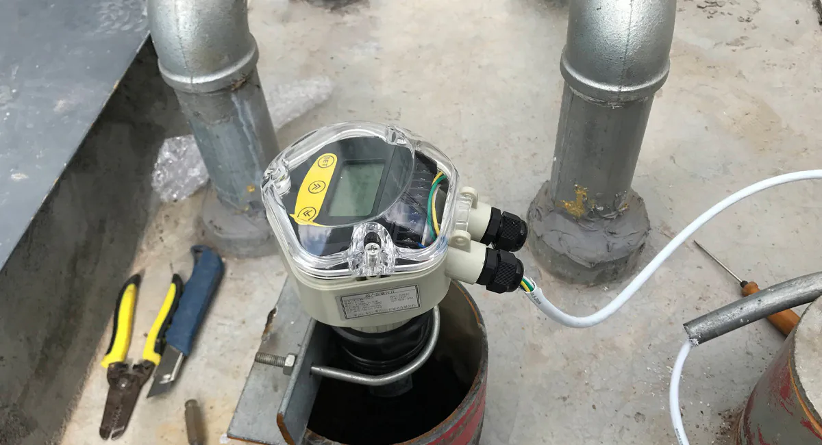
Ultrasonic Level Gauge: Working Principle, Core Technologies, Industrial Challenges, and Future Development in Industry 4.0
Введение
Level measurement is one of the most critical functions in industrial automation. Industries such as water treatment, chemical processing, food and beverage production, mining, oil storage, and municipal infrastructure rely on accurate level monitoring to ensure safe operation, inventory management, and process optimization.
Among various level measurement technologies, Ultrasonic Level Gauges have become one of the most widely used non-contact solutions. By measuring the travel time of sound waves reflected from a liquid or solid surface, ultrasonic sensors provide reliable level measurement without direct contact with the process medium.
As industrial facilities continue to embrace digitalization, Industrial IoT, Artificial Intelligence (AI), and Digital Twins, ultrasonic level measurement technology is evolving from a simple distance sensor into an intelligent component of modern industrial ecosystems.
Why Did Ultrasonic Level Measurement Evolve?
Early Mechanical Measurement Methods
Before electronic instrumentation became widespread, industries primarily relied on:
- Float gauges
- Sight glasses
- Dipsticks
- Mechanical tape systems
Although simple and inexpensive, these methods suffered from several limitations:
- Frequent maintenance requirements
- Mechanical wear
- Ограниченная точность
- Inability to support remote monitoring
- Safety concerns in hazardous environments
As industrial facilities expanded, operators needed continuous, automated, and remote level monitoring solutions.
Emergence of Contact Sensors
Technologies such as differential pressure transmitters, capacitance probes, and conductivity sensors improved automation but introduced new challenges.
Many industrial processes involve:
- Corrosive chemicals
- Toxic liquids
- Hygienic products
- High-temperature media
- Sticky or viscous substances
Direct sensor contact with these materials often led to contamination, corrosion, fouling, or shortened service life.
Why Ultrasonic Technology Became Popular
The development of piezoelectric ultrasonic transducers enabled engineers to measure level indirectly by determining the distance between the sensor and the material surface.
This non-contact approach offered significant advantages:
- No product contamination
- Reduced maintenance
- Improved safety
- Lower lifecycle costs
As a result, ultrasonic technology quickly became popular across multiple industries.
How Does an Ultrasonic Level Gauge Work?
Operating Principle
The core principle of the ultrasonic level gauge is Time-of-Flight (ToF). The transducer (sensor) emits high-frequency ultrasonic pulses toward the surface of the measured medium. The sound waves are reflected by the medium’s surface and return to the receiver. By measuring the round-trip propagation time $t$ of the sound wave in the air, combined with the speed of sound $v$, the distance $D$ can be calculated:
Combined with the known installation height $H$, the actual material or liquid level $L$ is determined as:
Evolution and Underlying Logic
This principle did not mature overnight. It underwent three core evolutionary stages driven by specific industrial needs:
Initial Stage: Continuous Wave (CW) Doppler and Interferometry
Evolutionary Process: Early acoustic measurements borrowed heavily from sonar technology, utilizing continuous waves for Doppler frequency shift or phase interferometry measurements.
The Logic Behind It: Continuous waves inside sealed, confined industrial vessels create severe multipath reflections and standing wave interference. This causes signals to cancel each other out or superimpose erroneously. To pinpoint a specific surface inside complex industrial spaces, the technology inevitably shifted toward pulsed signals.
Developmental Stage: Single-Frequency Pulsed ToF (Single-Transducer Integration)
Evolutionary Process: The technology evolved to emit short pulse signals (such as $40\text{ kHz}$) and transitioned from dual transducers (one transmitter, one receiver) to a single integrated transducer performing both functions.
The Logic Behind It: Dual transducers were bulky, difficult to install, and suffered from measurement blind spots caused by the intersecting beam angles. Integrating them into a single transducer leveraged the reversible piezoelectric effect (converting electrical energy to acoustic energy and vice versa). However, this introduced a new problem: after emitting a pulse, the mechanical ringing (residual oscillation) of the transducer prevents it from immediately receiving the return echo, thereby creating a measurement blind zone.
Modern Stage: Variable/Modulated Pulse and Digital Signal Coding (Fusion with Guided Wave/TDR Concepts)
Evolutionary Process: Modern ultrasonic devices no longer use rigid, single-frequency pulses. Instead, they implement pseudo-random codes, ultra-narrow pulses, and frequency modulation techniques (such as Chirp pulses).
The Logic Behind It: Industrial environments are filled with mechanical noise from motors and valves, which easily disrupts single-frequency systems. By “coding” or modulating the frequency of the pulse, the receiving end can decode the signal using correlation algorithms. This allows the device to precisely isolate its own echo out of a “noisy” industrial background.
Core Technologies of Modern Ultrasonic Level Gauges
Piezoelectric Ultrasonic Transducer Technology
The transducer is responsible for converting electrical signals into ultrasonic pulses and receiving reflected echoes.
Преимущества
- Высокая чувствительность
- Длительный срок службы
- Быстрое время отклика
- Низкое энергопотребление
Industry Problems Solved
Municipal water systems often require hundreds of measurement points.
Piezoelectric transducers provide reliable performance while maintaining low ownership costs.
Advanced Echo Processing Algorithms
Industrial tanks frequently contain structures that generate unwanted reflections.
Common sources include:
- Agitators
- Internal pipes
- Support beams
- Tank walls
Modern ultrasonic transmitters use advanced Digital Signal Processing (DSP) algorithms to identify the true surface echo.
Преимущества
- Improved accuracy
- False echo suppression
- Better performance in complex vessels
Industry Problems Solved
Chemical reactors and mixing tanks often contain multiple internal structures.
Advanced echo processing prevents false measurements caused by reflected signals.
Автоматическая температурная компенсация
The speed of sound varies significantly with temperature.
Примеры:
- 0°C: approximately 331 m/s
- 20°C: approximately 343 m/s
- 50°C: approximately 361 m/s
Without compensation, temperature changes would introduce significant measurement errors.
Преимущества
- Improved accuracy
- Stable outdoor operation
- Reduced seasonal drift
Industry Problems Solved
Water reservoirs and outdoor storage tanks experience large environmental temperature variations.
Temperature compensation ensures reliable operation year-round.
Narrow Beam Acoustic Focusing
Modern ultrasonic sensors use optimized transducer designs to focus acoustic energy into narrower beams.
Преимущества
- Reduced interference
- Improved signal strength
- Better target detection
Industry Problems Solved
Narrow tanks, channels, and confined process vessels often generate multiple reflections.
Focused acoustic beams improve measurement stability.
Intelligent Noise Filtering
Industrial environments are filled with acoustic and mechanical noise.
Sources include:
- Pumps
- Compressors
- Моторы
- Fans
Adaptive filtering algorithms help distinguish valid echoes from background interference.
Преимущества
- Improved signal stability
- Better reliability
- Reduced measurement fluctuations
Industry Problems Solved
Pump stations and wastewater treatment plants frequently experience vibration and noise interference.
Noise filtering improves overall measurement quality.
What Industrial Problems Do Ultrasonic Level Gauges Solve?
Очистка воды и сточных вод
Industry Challenge
Wastewater often contains:
- Corrosive substances
- Floating debris
- Biological contamination
- Variable flow conditions
Contact sensors frequently suffer from fouling and maintenance issues.
Solution
Non-contact ultrasonic sensors eliminate direct exposure to the process medium, reducing maintenance requirements while maintaining reliable operation.
Municipal Water Management
Industry Challenge
Cities require continuous monitoring of:
- Reservoir levels
- Pump stations
- Stormwater systems
- Flood control infrastructure
Solution
Ultrasonic level gauges provide economical remote monitoring with excellent long-term reliability.
Химическая обработка
Industry Challenge
Many chemicals are aggressive and highly corrosive.
Sensor degradation can result in costly downtime and maintenance.
Solution
Since ultrasonic sensors do not contact the process medium, they significantly reduce corrosion-related failures.
Food and Beverage Industry
Industry Challenge
Strict hygiene regulations require contamination-free measurement.
Solution
Non-contact measurement supports sanitary production processes while minimizing cleaning requirements.
Bulk Solids and Mining
Industry Challenge
Storage silos containing grain, cement, coal, and minerals require continuous inventory monitoring.
Solution
Ultrasonic technology provides economical level monitoring for many bulk solids applications.
Current Technical Bottlenecks
Vapor and Condensation Effects
Heavy vapor can absorb ultrasonic energy and reduce signal strength.
Industries affected include:
- Boiler systems
- Химические реакторы
- Food processing facilities
Foam Interference
Foam can absorb or scatter acoustic energy.
Common applications include:
- Fermentation tanks
- Очистка сточных вод
- Химические реакторы
This may reduce measurement stability.
Dust and Bulk Solids Challenges
Airborne dust in industries such as mining and cement production can weaken ultrasonic signals.
In extreme conditions, radar technology may provide superior performance.
Extreme Temperature Applications
Very high temperatures can alter sound propagation characteristics and affect measurement accuracy.
Limited Long-Distance Performance
Ultrasonic signals gradually weaken over distance.
For tanks exceeding 20–30 meters, radar level transmitters are often preferred.
Development in the Industry 4.0 and AI Era
Under the impetus of Industry 4.0 (IIoT) and Artificial Intelligence (AI), the ultrasonic level gauge is transitioning from a passive “Sensor” into a “Smart Node” equipped with edge computing capabilities.
1. Edge AI Echo Discrimination (TinyML)
Traditional ultrasonic level gauges rely on manually configured threshold lines or fixed window filters to block out agitator interference. In the AI era, transmitter microchips embed lightweight neural networks (TinyML).
The Transformation: By training on massive datasets of echo waveforms, the sensor can autonomously identify the differences between a true liquid level return, foam scattering, and an agitator blade obstacle. It can even diagnose process anomalies (such as boiling or boiling over) based on wave dynamics, removing the need for manual, on-site commissioning.
2. Predictive Maintenance and Prognostics and Health Management (PHM)
Industry 4.0 prioritizes “Zero Downtime” on production lines.
The Transformation: Intelligent ultrasonic level gauges continuously monitor their own structural health. For instance, by evaluating the electrical impedance spectrum of the piezoelectric ceramic, an internal AI can predict whether the matching layer is wearing down, scaling over, or aging. By monitoring current consumption in the transmission loop, it can predict hardware failures weeks before they happen, automatically pushing maintenance tickets to the cloud.
3. Native Digital Communication Protocols and Digital Twins
The Transformation: Next-generation instruments natively integrate OPC UA, Ethernet/IP, PROFINET, and advanced physical layer technologies like Ethernet-APL или WirelessHART. Instead of transmitting a single, isolated 4-20mA analog loop, they transmit a comprehensive data model containing temperature, signal-to-noise ratios (SNR), raw waveform profiles, and device asset data. This high-fidelity data feeds directly into cloud-based Digital Twin architectures, replicating vessel levels and instrument health status in virtual factory frameworks in real time.
Recommended Ultrasonic Level Gauge Selection by Industry
| Target Industry | Process Conditions & Characteristics | Recommended Product Type | Core Technical Parameter Requirements |
| Municipal Water & Sewage | Open-air, humid, short-to-medium range ($0-10\text{ m}$). | Integrated Standard Ultrasonic Level Gauge | – Range: $4\text{ m}, 8\text{ m}, 12\text{ m}$ – Blind Zone: $\le 0.25\text{ m}$ – Ingress Protection: IP68 – Точность: $\pm0.2\%\text{ FS}$ – Выход: 4-20mA, Modbus RTU |
| Chemical Storage Tanks | Corrosive, agitating, medium range ($0-15\text{ m}$). | Explosion-Proof & Anti-Corrosive Type (Remote or Integrated) | – Material: PVDF or PTFE transducer housing – Explosion Protection: Ex d IIC T6 Gb / Ex ia IIC T6 Ga – Software: Advanced False Echo Filtering – Pressure Limit: $\le 0.3\text{ MPa}$ |
| Water Conservancy / Rivers | Long distance ($0-30\text{ m}$), remote outdoor power limits. | Long-Range, Low-Power Remote Level Gauge | – Range: $30\text{ m}$ или $40\text{ m}$ (operating frequency $\sim20\text{ kHz}$) – Power: 12V DC / 24V DC (supports low-power sleep cycles) – Blind Zone: $\le 0.8\text{ m}$ – Operating Temp: $-40^\circ\text{C}$ до $+70^\circ\text{C}$ (with external PT1000 compensation) |
| Open-Channel Flow Metering | Flume/weir integration, requires flow conversion math. | Open-Channel Flow Specialized Ultrasonic Gauge | – Software: Built-in formulas for Parshall flumes, V-notch weirs, etc. – Разрешение: $1\text{ mm}$ (high resolution ensuring precise flow calculation) – Blind Zone: $\le 0.2\text{ m}$ |
Ultrasonic vs Radar vs Magnetostrictive Level Measurement
| Технология | Типичная точность | Contact with Media | Suitable for Vapor | Suitable for Foam | Cost Level |
|---|---|---|---|---|---|
| Ультразвуковой уровнемер | ±0.25% to ±1% FS | Нет | Умеренный | Умеренный | Низкий |
| Radar Level Transmitter | ±1 mm to ±5 mm | Нет | Превосходно | Превосходно | Высокий |
| Магнитострикционный уровнемер | ±0.5 mm to ±1 mm | Да | Превосходно | Превосходно | Высокий |
| Дифференциальный преобразователь давления | ±0.1% to ±0.5% FS | Да | Хорошо | Хорошо | Средний |
Заключение
Ultrasonic Level Gauges have become one of the most widely used non-contact level measurement technologies because they provide reliable, economical, and maintenance-friendly measurement across a broad range of industrial applications.
Through advances in piezoelectric transducers, digital signal processing, temperature compensation, and intelligent filtering, modern ultrasonic instruments offer significantly improved performance compared with earlier generations.
As Industry 4.0, Industrial IoT, Digital Twins, and Artificial Intelligence continue to reshape industrial automation, ultrasonic level gauges will evolve beyond simple measurement devices into intelligent sensing platforms capable of supporting predictive maintenance, process optimization, and autonomous industrial operations.
What causes an ultrasonic level gauge to produce no echo signal or a weak signal, and how can these issues be resolved?
A “No Echo” (Loss of Signal) or weak signal alert occurs when the ultrasonic pulse either never returns to the transducer or returns with an amplitude below the detection threshold.
Распространенные причины:
Heavy Surface Foam: Thick, dense foam acts as an acoustic absorber, swallowing the acoustic energy rather than reflecting it.
Extreme Turbulence or Agitation: Violent liquid churning or sloped solid surfaces scatter the sound waves sideways instead of reflecting them straight up back to the transducer.
Transducer Contamination: Condensation, dust, or chemical crust buildup on the sensor face dampens the physical vibration of the piezoelectric crystal.
Excessive Measuring Distance: The target surface has moved beyond the maximum physical range of the device, and the signal has naturally attenuated.
Решения:
Install a Stilling Well / Bypass Pipe: For turbulent or foaming liquids, installing a perforated stilling well bypass pipe forces a calm, foam-free liquid surface for the acoustic beam.
Aiming Adjustment: Use an adjustable flange (gimbal joint) to tilt the transducer perpendicular to the material slope if measuring angled solids.
Sensor Cleaning: Regularly wipe down the transducer face with a damp cloth or soft solvent (ensure chemical compatibility).
Upsize the Transducer: Upgrade to a lower-frequency transducer (e.g., swapping a $40\text{ kHz}$ sensor for a $20\text{ kHz}$ variant) to deliver a higher-power burst that cuts through dusty or deep air spaces.
What causes an ultrasonic level gauge's readings to be unstable or fluctuating, and how can these issues be resolved?
Unstable readings occur when the internal processing software receives multiple conflicting echoes and struggles to lock onto the true product level.
Распространенные причины:
Internal Obstructions: In-tank structures like agitator blades, ladders, heating coils, or support beams crossing the path of the ultrasonic beam angle.
Electrical Electromagnetic Interference (EMI): High-voltage cables, Variable Frequency Drives (VFDs) running nearby, or poor grounding injecting noise into the signal line.
Air Currents & Vapor Layering: Rapid air cross-flow, pneumatic filling, or heavy thermal stratification bending or distorting the acoustic wavefront.
Решения:
False Echo Mapping (Suppress Backing Noise): Execute a “false echo storage” scan via the device menu while the tank is empty. This maps out static objects like ladders and instructs the software algorithm to ignore those fixed distances.
Optimize Position: Relocate the gauge away from the filling inlet and ensure the acoustic beam path clears all structural obstructions by at least 200 mm.
Shielding and Grounding: Use twisted, shielded pairs for signal wiring, run signal wires separate from high-power mains, and verify that the instrument chassis is properly tied to a clean plant ground.
Adjust Software Damping: Increase the integration/damping time constant in the transmitter parameters to smooth out transient spikes caused by surface rippling.
What causes a significant discrepancy between an ultrasonic level gauge's measured value and the actual value, and how can this issue be resolved?
A consistent scalar or shifting error indicates that the physics underlying the calculation ($D = \frac{v \cdot t}{2}$) is working with incorrect assumptions.
Распространенные причины:
Temperature Gradients: The onboard temperature sensor only measures the air temperature right at the sensor head. If the tank bottom is hot and the top is cold, the estimated average speed of sound will be wrong.
Volatile Gas Composition: If the tank headspace contains non-air gases (e.g., carbon dioxide, nitrogen, or alcohol vapors), the speed of sound drops or rises dramatically. For instance, the speed of sound in pure $CO_2$ is roughly 259 m/s, compared to 343 m/s in air.
Incorrect Baseline Calibration: Wrong parameters entered for empty tank height ($H$) or sensor offset.
Решения:
Manual Velocity Correction: If the gas environment is uniform but non-air, change the default speed of sound parameter in the device configurations to match the specific vapor composition.
Remote Temperature Sensors: For tall silos with extreme temperature layers, install an external average temperature probe mid-tank and feed it back to the transmitter for dynamic correction.
Re-verify Geometrics: Double-check your physical tape measurements against the programmed “Empty Distance” and “Full Scale” values.
What environmental factors affect an ultrasonic level gauge?
Because ultrasonic waves are physical, mechanical pressure waves, they are deeply linked to the environment they travel through.
Температура: Temperature directly controls air density, changing the speed of sound by approximately 0.6 m/s per °C. Without constant tracking, temperature shifts cause massive scale errors.
Pressure & Vacuum: Ultrasonic gauges cannot function in a vacuum because there are no air molecules to vibrate and carry the sound wave. High pressure modifies air density, which shifts acoustic impedance and can choke signal transmission.
Vapor and Steam: Heavy steam or vapor absorbs acoustic energy and causes rapid local changes in the speed of sound, creating shifting or completely lost echo signals.
Wind and Air Turbulence: Strong outdoor winds across open channels or heavy indoor blowers can physically blow the acoustic beam sideways, so it completely misses the transducer on its return trip.
What causes an ultrasonic level gauge to display a "blind zone" error or indicate that the measurement is "out of range," and how can these issues be resolved?
These errors signal that the target is either dangerously close to the sensor face or completely out of its physical zone of control.
[ Transducer Face ]
      │
      ▼  ◄─── BLIND ZONE (Unmeasurable Ring Down Area)
   ─────── ◄─── High Level Limit
      │
      │  ◄─── WORKING RANGE (Valid Measurements)
      ▼
   ─────── ◄─── Low Level Limit (Tank Bottom)
Распространенные причины:
Overfilling Into the Blind Zone: Liquid has risen into the sensor’s “dead band” / “blind zone” (typically the upper 0.2 to 0.8 meters). The sensor cannot transition from emitting to receiving fast enough, resulting in an error or locking up at its maximum reading.
Loss of Bottom Echo: The tank is completely empty, but because the floor is flat or sloped, the sound bounces away, leading the unit to think it is “Out of Range.”
Решения:
Install a Standpipe (Nozzle Extension): Mount the transducer on a raised nozzle pipe. This shifts the physical blind zone up inside the pipe neck, allowing the tank to be filled 100% without entering the dead band.
Re-configure Tank Floor Profiles: Adjust the low-level cutoff parameters or enable “Tank Bottom Tracking” logic in the transmitter settings so it registers a complete loss of echo at maximum distance safely as “0% Full.”
How should an ultrasonic level gauge be maintained?
Though non-contact devices require significantly less upkeep than contact mechanical systems, preventive maintenance keeps accuracy high and prevents unplanned downtime.
Maintenance Protocol:
| Interval | Action Items | Назначение |
| Ежемесячно | • Perform a visual check of the transducer face. • Clean off any accumulated condensation droplets, crystalline crusts, or dust. | Prevents signal dampening and blind zone distortion. |
| Ежеквартально | • Inspect cable entries, gland seals, and housing covers for moisture ingress. • Check terminal blocks for corrosion. | Prevents internal electronic shorts and signal looping. |
| Bi-Annually | • Run an diagnostic diagnostic to review the echo signal-to-noise ratio (SNR). • Re-verify the current “False Echo Map” if process modifications occurred. | Validates that background noise hasn’t changed over time. |
| Annually | • Perform a cross-reference validation (dip-tape measurement) at two distinct level points. • Recalibrate the temperature compensation loop. | Guarantees system tracking integrity and long-term instrument accuracy. |
Handling Note: Never use wire brushes, metal scrapers, or harsh abrasive cleaners on the transducer surface. The matching layer is precision-engineered and can be easily punctured or scored, which permanently ruins the beam pattern.
Почему стоит доверять Instrava?
Мы выбираем производителей, руководствуясь нейтральной и беспристрастной позицией, всегда ставя во главу угла ваши интересы.
Наше существование зависит от того, чтобы помочь вам найти товары, которые идеально соответствуют вашим потребностям.
Благодаря тому, что наша компания базируется в Китае, мы имеем возможность лично проводить проверки производственных объектов и качества продукции на месте.
Мы помогаем вам избежать контактов с посредниками, выдающими себя за заводы.
Мы обеспечиваем более бесперебойное послепродажное обслуживание, устраняя проблемы, связанные с разницей во времени, и задержки, которые часто возникают при непосредственном взаимодействии с заводами.
Наша многоязычная команда обеспечивает эффективное общение.
Для стартапа в сфере трейдинга каждое взаимодействие с клиентом — это ценная возможность, свидетельствующая о том, что вы готовы довериться нам и дать нам шанс проявить себя.
В эпоху цифровых технологий, несмотря на широкую доступность информации, заблуждения зачастую подрывают доверие между людьми.
«Инстрава» полностью опирается на доверие; это наша основная философия и основа нашего существования в обществе. Это фундаментальная основа нашего долгосрочного роста и нашей приверженности служению обществу.
Пожалуйста, доверьтесь нам.