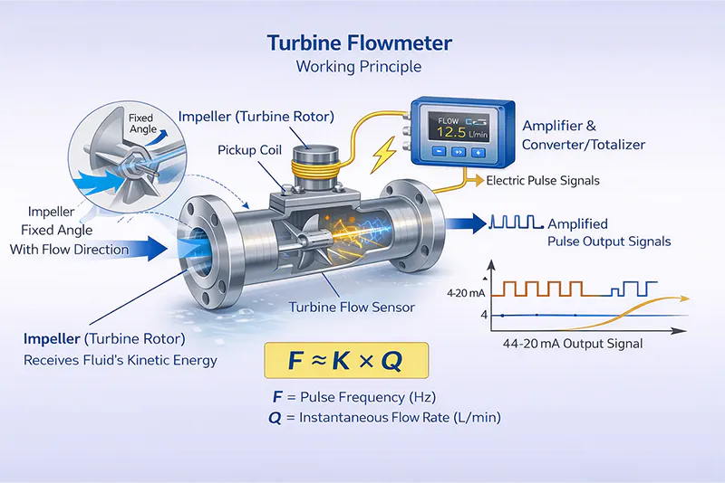
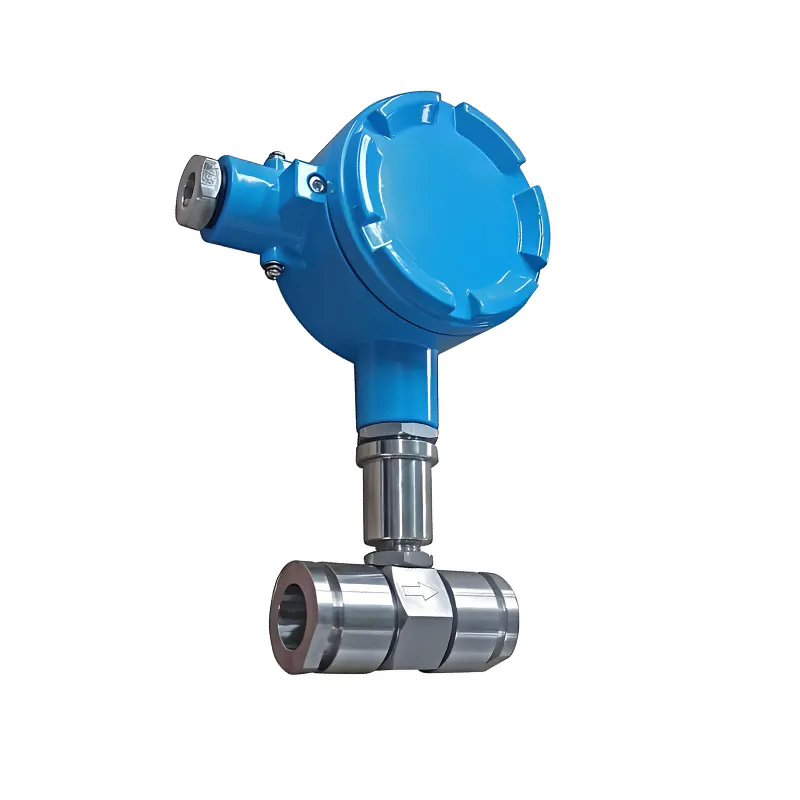
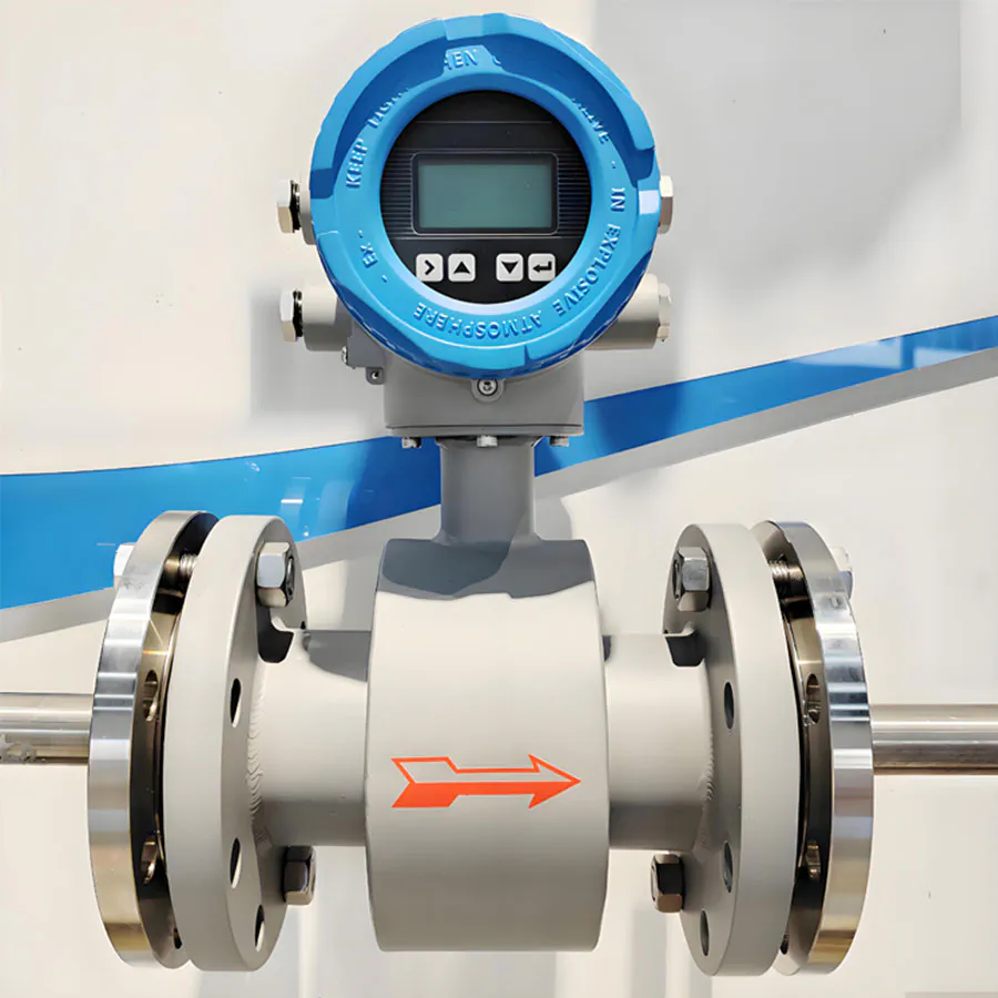
When the measured liquid flows through the turbine flow sensor, the impeller blades—mounted at a fixed angle to the flow direction—receive kinetic energy from the fluid.
As the impeller rotates, it reaches a stable speed once fluid driving torque, friction torque, and resistance torque are balanced. Under defined conditions, the rotational speed of the impeller is directly proportional to the average flow velocity inside the pipe.
Each rotation of the impeller periodically changes the magnetic field at the detection coil, generating an electrical pulse signal. After amplification and signal processing, the system outputs:
Pulse signal
4–20 mA analog signal
Instantaneous flow rate
Totalized flow
Within the calibrated flow range, the relationship between pulse frequency and flow rate is:
Within the calibrated flow range, the pulse frequency is directly proportional to the instantaneous flow rate:
Q = 3600 × F / K
Où ?
- Q — Instantaneous flow rate (m³/h)
- F — Pulse frequency (Hz)
- K — Instrument coefficient (pulses/m³), determined during calibration