
Accueil » Technologie » Industrial Voltage Transmitters: Optimizing Power Telemetry and Grid Compliance
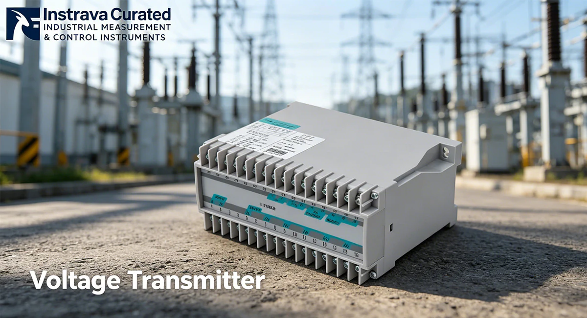
Industrial Voltage Transmitters: Optimizing Power Telemetry and Grid Compliance
1. Introduction: What is a Voltage Transmitter?
A Voltage Transmitter (also commonly referred to as a voltage transducer) is a high-precision electrical instrument engineered to detect alternating current (AC) or direct current (DC) voltage levels across a circuit and convert them into an isolated, standardized output signal. While basic voltmeters only display values locally, an industrial voltage transmitter scales voltage parameters into either stable analog signals (such as 4-20mA or 0-10V) or structured digital data packets via automated communication networks.
In modern multi-phase power distribution networks, monitoring line fluctuations is critical to protecting downstream infrastructure. A specialized three-phase voltage transmitter simultaneously samples the voltage waves of all three phases (L1, L2, L3) relative to Neutral or to each other. By mapping phase sags, swells, and imbalances in real time, these instruments act as vital telemetry nodes that feed accurate electrical data into Programmable Logic Controllers (PLCs), Supervisory Control and Data Acquisition (SCADA) systems, and Energy Management Systems (EMS).
2. Traditional Technology vs. Modern Transmitters in Harsh Industrial Environments
Industrial manufacturing plants, grid substations, and automated foundries expose electrical monitoring hardware to severe operating environments. Under High-Voltage Grid Fluctuations & Extreme Transient Electromagnetic Interference (EMI) Environments, traditional potential transformers (PTs) and legacy analog voltage sensors frequently fail.
Below are the three major problems encountered by traditional monitoring methods, along with the engineering mechanisms modern voltage transmitters use to solve them:
Problem 1: Core Saturation and Nonlinear Measurement Output During Voltage Swells
Traditional electromagnetic potential transformers rely heavily on iron cores that can experience magnetic saturation when exposed to sudden, severe voltage swells or transient overvoltages. When saturation occurs, the transformer’s output waveform becomes clipped and nonlinear, leading to severe measurement errors and rendering the telemetry data inaccurate during critical grid stress events.
The Voltage Transmitter Solution: Modern voltage transmitters utilize active, high-impedance solid-state sensing circuits combined with high-speed digital signal processors (DSPs). This architecture provides a wide dynamic input range that processes severe voltage swells linearly and without saturation, ensuring continuous, highly accurate True RMS voltage tracking even during severe grid disturbances.
Problem 2: Dielectric Breakdown and Component Failure from High-Voltage Spikes
Heavy industrial machinery—such as large inductive motors, arc furnaces, and power factor correction banks—injects massive transient voltage spikes ($dV/dt$) into local distribution networks. Traditional voltage sensors lack robust input protection, causing these high-voltage spikes to puncture internal insulation and lead to catastrophic short circuits and total instrument failure.
The Voltage Transmitter Solution: Industrial-grade voltage transmitters feature heavy-duty galvanic isolation (often rated up to 2500V AC or higher) between the high-voltage input channels, auxiliary power supply, and low-voltage output ports. Integrated Transient Voltage Suppressors (TVS) safely clamp incoming high-energy spikes, protecting the transmitter’s internal microprocessors and preventing dangerous voltages from migrating into downstream control equipment.
Problem 3: Signal Attenuation and Noise Corruption over Long Distances
Sending low-level analog voltage signals across a tightly packed factory floor introduces significant measurement errors. Electromagnetic fields from surrounding power lines inject common-mode noise into the analog lines, causing signal degradation and reading offsets at the control cabinet gateway.
The Voltage Transmitter Solution: Advanced voltage transmitters digitize voltage metrics directly at the measurement source. By transmitting data through an isolated RS485 interface running the Modbus RTU protocol, the physical voltage parameters are broadcast as high-speed digital differential signals. This digital transmission method is highly immune to EMI noise and maintains perfect data integrity over communication lines spanning up to 1200 meters.
3. International Parameters and Certification Matrix
To integrate safely into global industrial control systems, a voltage transmitter must meet stringent electrical specifications and international regulatory certifications.
Table 3.1: Baseline Technical Parameters
| Technical Parameter | Standard Engineering Specification |
| Input Configuration | Three-Phase Three-Wire (3P3W), Three-Phase Four-Wire (3P4W) |
| Voltage Input Range | Direct input up to 500V AC Line-to-Line (or higher via external PTs) |
| Précision de la mesure | Class 0.5 or Class 0.2S conforming to IEC 62053 standards |
| Galvanic Isolation Voltage | ≥ 2500V AC between Input, Output, and Power Supply ports |
| Interface de communication | RS485 Serial Port, standard Modbus RTU Protocol |
| Mounting Configuration | Standard 35mm DIN Rail (Conforming to DIN EN 50022) |
| Temps de réponse | ≤ 200 ms tracking latency |
Table 3.2: Sector-Specific Parameters & Certification Standards
| Industry Vertical | Target Parameter Requirements | Critical Certification Mandates |
| Renewable Energy (Solar / Wind Microgrids) | High frequency tracking (45-65 Hz); precise low-voltage ride-through (LVRT) monitoring down to 10% of nominal voltage. | CE Mark; UL 61010-1 Safety Certification; IEEE Grid Code Compliance |
| Data Centers & Critical Infrastructure | High-speed polling rates; sub-second zero-voltage crossing and phase-angle logging capability. | UL Listed / Recognized; FCC Part 15 Class B; RoHS Directive Compliance |
| Metallurgical & Chemical Smelting | Extended operating temperature limits (-20°C to +70°C); specialized high-humidity anti-corrosive coating options. | CE; Industrial Grade ISO 9001 Manufacturing Quality Standards |
4. Instrava Product Showcase: Application Scenario and Compliance Success
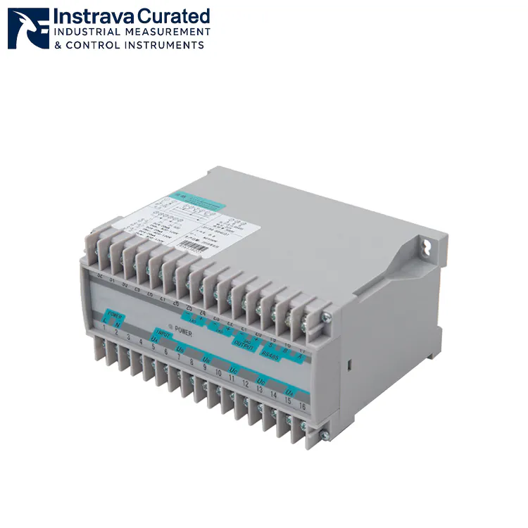
Le Instrava Three-Phase Voltage Transmitter with RS485 Modbus represents a major advancement in high-density power telemetry engineering. By packing a multi-channel, high-voltage acquisition module and a digital RS485 communication engine onto a compact DIN rail footprint, this transmitter eliminates the need for bulky analog transducers and complex wiring schemes.
Real-World Case Study: Resolving Voltage Telemetry Failures in a Remote Microgrid
The Challenge: A remote solar-plus-storage microgrid facility in Texas experienced recurring operational instability. During automated grid-switching sequences, localized voltage transients caused the facility’s existing analog monitoring sensors to output erratic voltage spikes. These false readings confused the central control PLC, causing it to trigger safety shutdowns and prematurely disconnect the main energy storage battery banks. This issue led to costly system downtime and strained compliance relations with the local utility provider. Additionally, the microgrid site required all control panel components to carry recognized third-party safety certifications to satisfy an upcoming municipal insurance audit.
The Solution: Site engineers replaced their legacy instrumentation with the Instrava Three-Phase Voltage Transmitter with RS485 Modbus. The unit was installed directly onto the 35mm DIN rail within the primary AC distribution cabinet. The L1, L2, L3, and Neutral lines were routed straight to the transmitter’s high-impedance input block via a set of 1A inline protection fuses. The transmitter’s digital RS485 port was then connected directly to the site’s main SCADA communication loop using a single shielded twisted-pair cable.
The Result: The integrated True RMS processing engine within the Instrava transmitter completely filtered out the grid-switching transient noise. Smooth, stable, and highly accurate digital voltage registers were streamed over Modbus RTU back to the master PLC panel. The 2500V AC galvanic isolation protected the sensitive low-voltage control network from high-voltage line surges, completely eliminating the false overvoltage trips. The microgrid successfully passed its safety compliance audit, and the facility stabilized its grid operations, preventing an estimated $15,000 in monthly operational revenue losses.
5. Installation Protocols and Environmental Thresholds
To ensure long-term field reliability and maintain Class 0.5 measurement accuracy, the physical installation of the three-phase voltage transmitter must follow precise electrical engineering standards:
Enclosure and Ambient Conditions: Lock the transmitter onto a secure section of 35mm DIN rail inside an electrical control enclosure. For indoor control rooms, an IP20 or IP51 rated cabinet is sufficient. If deploying in high-dust, high-humidity, or outdoor environments, the transmitter must be sealed inside a weatherproof IP65 or IP66 enclosure.
High-Voltage Input Wiring: Connect the phase lines (L1, L2, L3) and Neutral line (N) directly to the corresponding high-voltage terminal inputs on the device. For safety and short-circuit protection, a dedicated 3-pole or 4-pole circuit breaker or inline fast-acting fuses rated at 1A or 2A must be installed between the power lines and the transmitter inputs.
RS485 Communication Topology: Connect the RS485 network in a strict linear daisy-chain configuration from node to node. Avoid using star, tree, or long stub branch configurations, as these wiring styles introduce signal reflections that disrupt data packets. Use a high-quality Shielded Twisted Pair (STP) cable, and wire a 120-ohm termination resistor across the A and B communication terminals on the physically last device on the bus loop to match line impedance.
6. Preventative Maintenance and Operational Optimization
While solid-state voltage transmitters have no moving components and require minimal manual upkeep, regular preventative maintenance safeguards the system against external environmental wear:
Annual Terminal Torque Verifications: Continuous thermal expansion cycles and low-frequency plant vibrations can gradually loosen terminal screws over time. Technicians should conduct annual torque audits on all high-voltage input connections and power terminals using a calibrated insulated torque screwdriver to maintain the manufacturer’s specified tension.
Infrared Thermal Imaging Checks: During routine facility inspection windows, use a thermal imaging camera to scan the voltage transmitter cabinet under normal operating loads. Any concentrated heat signatures around terminal blocks indicate a loose wire contact or degradation that must be addressed immediately.
Dust and Contaminant Removal: In heavy manufacturing or wood-processing facilities, fine conductive dust can settle over the terminal gaps of the transmitter, creating potential high-resistance tracking paths. Use clean, dry, low-pressure compressed air to blow away accumulation during scheduled panel isolation maintenance windows.
Recommandations de produits connexes
Why is the three-phase voltage transmitter showing 0V on the RS485 Modbus registers when the primary power line is confirmed to be live?
A zero-voltage reading on the digital registers under a live line indicates an interruption in the input voltage path. Verify that the upstream protection fuses or inline circuit breakers feeding the transmitter’s input terminals have not tripped or blown. Next, use a digital multimeter to measure the AC voltage directly at the transmitter’s L1, L2, L3, and N terminals to confirm if line voltage is physically reaching the device inputs.
How can a field technician eliminate frequent Modbus communication timeouts or CRC packet errors on an Instrava voltage transmitter loop?
To resolve frequent RS485 Modbus timeouts or CRC errors, first confirm that a 120-ohm termination resistor is wired across the A and B data lines at the absolute physical end of the cable run. Second, verify that the RS485 cable shielding is grounded at only one single point—ideally at the master SCADA gateway panel—to prevent ground loops. Third, access the device settings to ensure that the transmitter is assigned a completely unique Modbus slave address that does not conflict with other hardware on the bus.
What are the risks of omitting inline fuses on the input connections of a three-phase voltage transmitter?
Omitting inline protection fuses on the voltage inputs presents a severe electrical safety hazard. If an extreme grid transient, lightning surge, or internal component fault triggers a short circuit within the device, the lack of fuses allows unrestricted fault current to flow through the monitoring lines. This can cause rapid thermal runaway, vaporize the input wiring, destroy the transmitter, and present an immediate risk of an arc-flash explosion or electrical panel fire.
What happens to the accuracy of a three-phase voltage transmitter if the Neutral wire is accidentally disconnected in a 3P4W configuration?
Disconnecting the Neutral wire in a Three-Phase Four-Wire (3P4W) system causes the internal reference point of the transmitter to float. If the phase loads across the power system are unbalanced, this floating neutral will cause the measured phase-to-neutral voltage readings to drift wildly, showing artificially high voltages on lightly loaded phases and artificially low voltages on heavily loaded phases, even though the actual line-to-line voltages remain stable.
Can the Instrava Three-Phase Voltage Transmitter be wired directly to a medium-voltage utility line (such as 11kV or 33kV)?
No, the Instrava Three-Phase Voltage Transmitter cannot be wired directly to medium-voltage utility lines. The direct input terminals of the transmitter are engineered for low-voltage systems, typically up to 500V AC line-to-line. Connecting medium-voltage lines directly to the device will cause immediate dielectric breakdown, completely destroy the internal circuitry, and trigger a catastrophic explosive short circuit. For medium-voltage networks, external step-down Potential Transformers (PTs) with a standardized 100V or 110V secondary output must be used to safely interface with the transmitter inputs.
Why is an RS485 Modbus output voltage transmitter preferred over a traditional analog 4-20mA voltage transducer in a modern industrial plant?
An RS485 Modbus output voltage transmitter is preferred over an analog 4-20mA transducer because a single digital unit can transmit comprehensive three-phase parameters—including Phase A, B, and C voltages, line frequencies, line-to-line values, and phase status alerts—simultaneously over a single shielded twisted-pair wire. In contrast, a traditional analog approach requires three separate transmitters and three dedicated sets of PLC analog input cards to monitor a three-phase system, which significantly increases hardware costs, installation footprints, and wiring complexity.
Pourquoi choisir Instrava ?
Construit sur la cohérence, pas sur les revendications
Axé sur les applications industrielles
Nous sommes spécialisés dans l'analyse et la détection industrielles, avec une compréhension claire des environnements d'exploitation et des exigences du monde réel.
Critères stricts de sélection des produits
Chaque instrument est évalué en fonction de ses performances, de sa stabilité et de son adéquation à l'application, et non pas seulement en fonction de ses spécifications ou de son prix.
Approvisionnement fiable et constance de la qualité
Nous travaillons avec des fabricants de confiance pour garantir un approvisionnement stable, une qualité constante et une livraison fiable.
Un soutien pratique et basé sur l'expérience
Nos recommandations sont fondées sur la compréhension des applications, ce qui permet aux clients d'éviter les problèmes courants et d'obtenir des résultats fiables.
Instrava est conçu pour réduire l'incertitude, afin que chaque décision que vous prenez soit plus claire, plus sûre et plus fiable.